CDB3318 Cirrus Logic Inc, CDB3318 Datasheet - Page 25
CDB3318
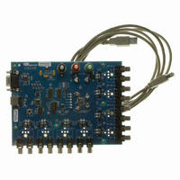
Manufacturer Part Number
CDB3318
Description
Eval Bd - 8-channel Digital Vol Cntrl
Manufacturer
Cirrus Logic Inc
Specifications of CDB3318
Main Purpose
Audio, Volume Control
Embedded
No
Utilized Ic / Part
CS3318
Primary Attributes
8 Single-Ended Analog Inputs and Outputs, USB or RS232 Interface
Secondary Attributes
Graphical User Interface
Description/function
Audio DSPs
Operating Supply Voltage
8 V to 9 V
Product
Audio Modules
Lead Free Status / RoHS Status
Contains lead / RoHS non-compliant
For Use With/related Products
CS3310
Lead Free Status / RoHS Status
Contains lead / RoHS non-compliant, Contains lead / RoHS non-compliant
Other names
598-1497


DS693F1
input of device N+1 may be repeated for up to 128 devices per single CS signal. If more than 128 devices
are required in a system, separate CS signals may be used to create additional chains of up to 128 devices
per CS signal.
As each device is placed into reset (RESET is low), its ENOut signal is driven low. The ENOut signal will
continue to be driven low until the device is taken out of reset (RESET is high) and the Enable bit (see
able Next Device (Bit 0)” on page
To configure a unique Individual device address for each device on the shared serial bus, the first device
must be reset (a low to high transition on its RESET pin), the Individual device address register must be
written (using the CS3318’s default device address) with a unique device address, and the Enable bit must
be set to take the next device in the serial control chain out of reset. This process may be repeated until all
devices in the serial control chain have been assigned a new Individual device address.
grams this configuration process.
Notice that
discrete steps. While this demonstrates one approach to device configuration, it should be noted that two
steps are not necessary to complete the action of setting the Individual address and enabling the next de-
vice. This may be done simultaneously with one register write (containing the new Individual address and
the Enable bit set) to the Individual address register.
unique Individual chip adress
devices in a chain, setting a
This loop steps through the
Using the new Individual chip address,
for each device as it
perform a write cycle to set the Enable
progresses.
Figure 10
bit.
Figure 10. Individual Device Address Configuration Process
bringing the next device in the
ENout pin to be driven high,
shows the setting of the Individual address and the setting of the Enable bit as two
chain out of its reset state.
This will cause the device's
No
41) is set, at which time the ENOut signal will be driven high.
Optionally, device configuration (initial
etc.) may be implemented using the
Individual chip address register to a
perform a write cycle to change the
volume settings, Group addresses,
Using the default chip address,
new Individual device address.
chain been assigned a unique
Have all the devices in the
Reset the First Device
Apply System Power
chip address?
unique value.
in the Chain
Start
Yes
addressed with this new Individual device address.
device are set to their default value. The
ENout pin on each device is low, holding
each subsequent device in a reset state.
A device will also respond to register writes when
At this point, the chip addresses of each
addressed with its Group 1 or Group 2 address.
serial bus using the device's assigned
From this point forward, the device will only
independently adressed through the
respond to register reads and writes when
communicate with each device in parallel, but each
device will only respond when the first byte clocked
The Reset input pins of all devices in the chain are
in on the serial control bus matches its Individual,
clocked in does not match the one of the device's
Each device may now be
Group 1 or Group 2 address. If the first byte
unique chip address.
now high. The serial control interface will
chip addresses, the device will ignore all
subsequent traffic on the bus until a new
communication cycle is initiated.
Figure 10
CS3318
“En-
dia-
25
Related parts for CDB3318
Image
Part Number
Description
Manufacturer
Datasheet
Request
R

Part Number:
Description:
Development Kit
Manufacturer:
Cirrus Logic Inc
Datasheet:
Part Number:
Description:
Development Kit
Manufacturer:
Cirrus Logic Inc
Datasheet:


Part Number:
Description:
High-efficiency PFC + Fluorescent Lamp Driver Reference Design
Manufacturer:
Cirrus Logic Inc
Datasheet:
Part Number:
Description:
Development Kit
Manufacturer:
Cirrus Logic Inc
Datasheet:
Part Number:
Description:
Development Kit
Manufacturer:
Cirrus Logic Inc
Datasheet:

Part Number:
Description:
Development Kit
Manufacturer:
Cirrus Logic Inc
Datasheet:
Part Number:
Description:
Development Kit
Manufacturer:
Cirrus Logic Inc
Datasheet:
Part Number:
Description:
Development Kit
Manufacturer:
Cirrus Logic Inc
Datasheet:
Part Number:
Description:
Development Kit
Manufacturer:
Cirrus Logic Inc
Datasheet:

Part Number:
Description:
EVALUATION BOARD FOR CS8427
Manufacturer:
Cirrus Logic Inc
Datasheet:

Part Number:
Description:
BOARD EVAL FOR CS8416 RCVR
Manufacturer:
Cirrus Logic Inc
Datasheet:

Part Number:
Description:
EVALUATION BOARD FOR CS8420
Manufacturer:
Cirrus Logic Inc
Datasheet:

Part Number:
Description:
KIT DEVELOPMENT EP9315 ARM9
Manufacturer:
Cirrus Logic Inc
Datasheet:

Part Number:
Description:
KIT DEVELOPMENT EP9302 ARM9
Manufacturer:
Cirrus Logic Inc
Datasheet: