USBIO24 ELEXOL, USBIO24 Datasheet
USBIO24
Specifications of USBIO24


Related parts for USBIO24


USBIO24 Summary of contents
Page 1
... USBIO24 R Digital I/O Module The USBIO24 R is the ROHS Compliant version of our previous USB I/O 24 range. The USB I low-cost integrated module for the input and/or output of digital signals from a computer system by connection to the USB port. The modules I/O Port pin out and firmware are compatible with the previous versions of the USB I/O24 modules ...
Page 2
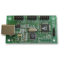
... Simple command set for easy control of ports and data transfer. Module Layout and Physical Dimensions Shown in the diagram below is the module layout along with the physical dimensions of the unit. 38.2 mm 22.9 mm 10.9 mm 4.2 mm All Hole sizes 3.5mm dia 29.8 mm Elexol Pty Ltd Version 1.1 USB I Datasheet Page 2 http://www.elexol.com ...
Page 3
... I/O2 I/O Programmable I/O pin with bit value I/O1 I/O Programmable I/O pin with bit value GND PWR Ground signal USB BUS and all I/O Elexol Pty Ltd Version 1.1 USB I Datasheet USB END VCC I/O8 I/O7 I/O6 I/O5 I/O4 I/O3 ...
Page 4
... Note: In USB powered mode this pin is linked to pin External power needs to be applied when in Bus powered mode** 3 GND PWR Ground signal USB BUS and all I/O Elexol Pty Ltd Version 1.1 USB I Datasheet USB END VDD VCC GND DESCRIPTION Page 4 http://www ...
Page 5
... Follow with Port write and binary data ‘2’ ‘1’ The commands in the above table are in ASCII format. All Data is sent in Binary format. Pull Up Elexol Pty Ltd Version 1.1 USB I Datasheet FUNCTION Identify Device Write to Port A Write to Port B ...
Page 6
... All reads have a port designator (‘a’, ’b’ or ’c’) before the data. All auto sends have a port designator (‘a’, ’b’ or ’c’) before the data. All writes to the port that change the port will results in a port data auto send. Elexol Pty Ltd Version 1.1 USB I Datasheet Page 6 http://www ...
Page 7
... MSComm1.Output = "S" + Chr$(255) //S FF MSComm1.Output = "S" + Chr$(170) //S AA MSComm1.Output = "S" + Chr$(85) 3. Each byte returned from the SPI will have a preceding "S" character and then the byte value from the SPI device. Elexol Pty Ltd Version 1.1 USB I Datasheet REPLY 1 Byte of data received on ...
Page 8
... Note: you may have to send out leading zero's and don't cares depending on device you are communicating with. e.g. seven leading zero's then a start bit as per the image below. Example image for SPI communications with the MCP3004/3008 using 8 bit segments taken from the MCP3004./3008 datasheet. (http://www.microchip.com) Elexol Pty Ltd Version 1.1 USB I Datasheet Page 8 ...
Page 9
... Upgrades Upgrades are available to run the SX48 at 50MHz clock speed instead of using the internal 4MHz clock. Accessory Boards Accessory boards are available for this product. Please check the Elexol website for further information. Elexol Pty Ltd Version 1.1 USB I Datasheet ...
Page 10
... Connect the USBIO24 and windows will automatically ask for the driver, select to specify a location and browse to the directory where you have unzipped the files. (Use of the Non Plug & Play driver for the USBIO24 is recommended to avoid a delay on connecting the USBIO24 ) Once the Virtual COM Port is installed it can be programmed exactly as a regular serial COM port using the MSComm control from within VB or API calls from C or other languages ...
Page 11
... Programming the USBIO24 from Visual Basic using the Virtual COM Port. To operate the USBIO24 from within Visual Basic it is best to use the Microsoft MSComm control to access the COM port. To input data from the USBIO24 you must use the port in binary mode and receiving the data is a bit convoluted. ...
Page 12
... MSComm1.Output = "a" ‘ Request data from port Timer ‘ Use the Timer to allow the program to continue if there is an error While Timer < 0.4 And MSComm1.InBufferCount < 1 Wend If MSComm1.InBufferCount <> 1 Then Call MsgBox("Read Timeout", vbInformation, "USBIO24 VERSION 3 Error") Exit Sub End If Dim TempBuffer As Variant Dim ByteBuffer() As Byte TempBuffer = MSComm1 ...
Page 13
... The SX48 draws it power from its own external power supply, but the voltage provided by the power supply can be either set to the desired 3.3V or regulated by a 3.3V regulator. Note: This 3.3V regulator is not currently placed on the board and is only provided as a separate option. Elexol Pty Ltd Version 1.1 USB I Datasheet Page 13 http://www ...
Page 14
... Links VSX Power rail, can be removed if the unit requires power switching to be used during USB Suspend. Note when using Power switching the soft start up circuit needs to be place (R3 and C10) RTCC = Connected to the RTCC pin on the SX48. Elexol Pty Ltd Version 1.1 USB I Datasheet Link 2 Link 3 Link 1 Page 14 http://www ...
Page 15
... Schematic C PORT Vdd 46 Vdd 32 Vdd 18 Vdd 4 Elexol Pty Ltd Version 1.1 USB I Datasheet B PORT A PORT Vss 47 Vss 33 Vss 19 Vss 5 RTCC 48 TEST 26 GND 21 GND 18 GND 7 AGND 25 5 Page 15 http://www.elexol.com ...
Page 16
... Total Current to or from Any PORT (8 Single I/O make a PORT) 50mA Total Current in or out of all the module’s I/O pins Further Reading and Examples More information and examples for the USBIO24 can be found on our websites at Updated drivers and further information about the USB interface chip can be found at the FTDI website www ...
Page 17
... Australia Product Use Limitations, Warranty and Quality Statement. The USBIO24 should not be used in any situation where it’s failure or failure of the PC or software controlling it could cause human injury or severe damage to equipment. This device is not designed for or intended to be used in any life critical application. ...