PC4-200P Amphenol Industrial Operations, PC4-200P Datasheet - Page 6
PC4-200P
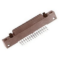
Manufacturer Part Number
PC4-200P
Description
BOARD-BOARD CONNECTOR PLUG, 200WAY, 4ROW
Manufacturer
Amphenol Industrial Operations
Datasheet
1.DB3-030P.pdf
(23 pages)
Specifications of PC4-200P
Pitch Spacing
2.54mm
No. Of Rows
4
No. Of Contacts
200
Gender
Plug
Contact Termination
Right Angle Through Hole
Contact Plating
Tin
Connector Type
Board To Board
Contact Material
Copper Alloy


Low Mating Force
contact installation instructions,
Individual contacts in the B
can be removed and replaced, thereby avoiding replacement
of the entire connector.
TOOLS REQUIRED:
MB, PC Series
IO Series
CONTACT REMOVAL - DB SERIES
Contact removal is accomplished from the front or mating
side of this connector series without removing the entire con-
nector from the printed circuit board. Determine which con-
tact is to be removed from the connector and cut tail.
Unsolder cut tail. Solder sucking may be necessary to clear
the printed circuit board of solder and cut tail.
Pull the contact through the front side of the connector with
tweezers. Care must be taken not to damage adjacent con-
tacts. Discard the damaged contact.
CONTACT REPLACEMENT/INSERTION - DB SERIES
Using tweezers or fingers, carefully place the replacement
contact TAIL FIRST into the appropriate contact cavity in the
front of the connector. Before final seating of the contact
make provisions for proper dressing of the contact, since the
90° tail of the DB connector must be routed through its nest in
the connector body molding and, in turn, into the printed cir-
cuit board hole.
Push the contact into the cavity with a flat-edged rod of .060
to .100 inch diameter until contact seats. Do not push against
bristle wires or bend shroud. It may be necessary to simulta-
neously bend the contact tail during this step. Dress and
resolder contact tail in proper location.
CONTACT REMOVAL - MB, PC SERIES**
Contact removal is accomplished from the front or mating
side of these connector series without removing the entire
connector from the printed circuit board. Determine which
contact is to be removed from the connector and unsolder or
unwrap the contact tail as applicable. Tail cutting and/or sol-
der sucking may be necessary to clear the printed circuit
board.
Inspect the damaged contact to determine if the bristle wires
are bent in a particular direction within the contact cavity. The
slot in the tube end of the 11-10368 Extraction Tool is
designed to accommodate these bent strands.
Retract the plunger of the 11-10368 Extraction Tool to its fur-
thest point of travel, and line up the slot in the tube end with
any bent bristle wires in the contact cavity. Insert the tool into
contact cavity. A moderate amount of resistance will be
encountered until the contact retention tines are deflected,
and then a positive stop will be felt.
* Available from Amphenol Corporation, Amphenol Aerospace, Sid-
** Except for MB with compliant contacts; consult Amphenol, Sidney,
ney NY 13838-1395. FSCM 77820
NY for details.
11-10368 Tool*
11-10372 Insertion Tool*
solder removal equipment
M22520/2-01 Crimp Tool
Daniels Tool #K743 Positioner
10-296943-22 Removal Tool
10-296940-22 Insertion Tool
3
Low Mating Force Connector line
10
11-10368 EXTRACTION TOOL AND 11-10372 INSERTION TOOL
INSERT EXTRACTION TOOL WITH PLUNGER RETRACTED
REMOVE DAMAGED CONTACT
repair/replacement
Related parts for PC4-200P
Image
Part Number
Description
Manufacturer
Datasheet
Request
R

Part Number:
Description:
AMPHENOL
Manufacturer:
Amphenol Industrial Operations
Datasheet:

Part Number:
Description:
CIRCULAR INSERT, PIN, 2WAY, SOLDER
Manufacturer:
Amphenol Industrial Operations
Datasheet:

Part Number:
Description:
CIRCULAR INSERT, SOCKET, 2WAY, SOLDER
Manufacturer:
Amphenol Industrial Operations
Datasheet:
Part Number:
Description:
CIRCULAR INSERT, SOCKET, 3WAY, SOLDER
Manufacturer:
Amphenol Industrial Operations
Datasheet:
Part Number:
Description:
CIRCULAR INSERT, PIN, 2WAY, SOLDER
Manufacturer:
Amphenol Industrial Operations
Datasheet:

Part Number:
Description:
JAM NUT CONN, RCPT, SIZE 9, 6POS, PANEL
Manufacturer:
Amphenol Industrial Operations
Datasheet:
Part Number:
Description:
PT 41C 41#20 PIN RECP
Manufacturer:
Amphenol Industrial Operations
Part Number:
Description:
PT 41C 41#20 SKT RECP
Manufacturer:
Amphenol Industrial Operations