S-2404H-CCT Cinch Connectors, S-2404H-CCT Datasheet
S-2404H-CCT
Specifications of S-2404H-CCT


Related parts for S-2404H-CCT


S-2404H-CCT Summary of contents
Page 1
... COMMERCIAL Barrier Blocks Circular Mini DIN BNC Jones Plugs Edge Connectors ...
Page 2
... Available in sizes 3 through 8 contact, the Cinch Mini Din family includes a fully shielded cable mounted plug in various cable lengths or cable mounted plug components for customers with high-volume assembly and overmold capabilities. ...
Page 3
... Interposing barriers between terminals yield higher electrical ratings and provide additional protection against frayed wire shorting. ■ A wide variety of barrier blocks makes it possible to select the combination of mechanical and electrical characteristics that best meet the exact requirements of your application. ■ A wide selection of optional terminals and fanning strips permits the equipment designer to choose the method of termination most suitable for his environmental specifications and manufacturing requirements ...
Page 4
... Barrier Blocks TERMINAL BLOCK QUICK REFERENCE Center-to- Number Single or Center of Double Screw Operating Series Spacing Terminals Row Size 140 .375 1-25 Double 5-40 141 .438 1-20 Double 6-32 142 .563 1-17 Double 8-32 150 .688 1-10 Double 10-32 151 .875 1-8 ...
Page 5
... Barrier Blocks Series 140 Electrical Characteristics Voltage Rating: 250 VAC RMS maximum Current Rating: 15 Amps maximum Maximum Watts Per Terminal: 3750 Mechanical Characteristics Maximum Wire Size: #16 AWG Recommended Tightening Torque: 9 lb.-in. Dimensions Ordering Information No. of Terminals Call Toll Free: 1 (800) 323-9612 .375 Density, 5-40 x 3/16" ...
Page 6
... Solder Terminals can be ordered separately. Terminal Type “Y” “3/4W” “W” .375 Density, 5-40 x 3/16" BH Screw, Open Bottom, Double Row “3/4W” Terminals Catalog No. 1-140-Y 1-140-3/4W 2-140-Y 2-140-3/4W 3-140-Y 3-140-3/4W 4-140-Y 4-140-3/4W 5-140-Y 5-140-3/4W 6-140-Y 6-140-3/4W 7-140-Y 7-140-3/4W 8-140-Y ...
Page 7
... Use Standard Marker Strips for “3/4W” and “W” Solder Terminals. Accessories • Jumpers • Fanning Strips Call Toll Free: 1 (800) 323-9612 .375 Density, 5-40 x 3/16" BH Screw, Open Bottom, Double Row Catalog No. Catalog No. MS-1-140 MS-1-140-Y MS-2-140 MS-2-140-Y MS-3-140 MS-3-140-Y MS-4-140 ...
Page 8
... Barrier Blocks Series 141 Electrical Characteristics Voltage Rating: 250 VAC RMS maximum Current Rating: 20 Amps maximum Maximum Watts Per Terminal: 5000 Mechanical Characteristics Maximum Wire Size: #14 AWG Recommended Tightening Torque: 12 lb.-in. Dimensions Ordering Information No. of Terminals Call Toll Free: 1 (800) 323-9612 .438 Density, 6-32 x 1/4" ...
Page 9
... Solder Terminals can be ordered separately. Terminal Type “Y” “3/4W” “W” .438 Density, 6-32 x 1/4" BH Screw, Open Bottom, Double Row “3/4W” Terminals “W” Terminals Catalog No. Catalog No. 1-141-3/4W 1-141-W 2-141-3/4W ...
Page 10
... Use Standard Marker Strip for “3/4W” and “W” Solder Terminals. Accessories • Jumpers • Fanning Strips Call Toll Free: 1 (800) 323-9612 .438 Density, 6-32 x 1/4" BH Screw, Open Bottom, Double Row “Y” Terminal Catalog No. Catalog No. MS-1-141 MS-1-141-Y MS-2-141 MS-2-141-Y ...
Page 11
... Barrier Blocks Series 142 Electrical Characteristics Voltage Rating: 250 VAC RMS maximum Current Rating: 30 Amps maximum Maximum Watts Per Terminal: 7500 Mechanical Characteristics Maximum Wire Size: #10 AWG Recommended Tightening Torque: 16 lb.-in. Dimensions Ordering Information No. of Terminals Call Toll Free: 1 (800) 323-9612 .563 Density, 8-32 x 5/16" ...
Page 12
... Solder Terminals can be ordered separately. Terminal Type “Y” “3/4W” “W” .563 Density, 8-32 x 5/16" BH Screw, Open Bottom, Double Row “3/4W” Terminals Catalog No. 1-142-Y 1-142-3/4W 2-142-Y 2-142-3/4W 3-142-Y 3-142-3/4W 4-142-Y ...
Page 13
... Terminals Use Standard Marker Strips for “3/4W” and “W” Solder Terminals. Accessories • Jumpers • Fanning Strips Call Toll Free: 1 (800) 323-9612 .563 Density, 8-32 x 5/16" BH Screw, Open Bottom, Double Row Catalog No. Catalog No. MS-1-142 MS-1-142-Y MS-2-142 MS-2-142-Y MS-3-142 MS-3-142-Y ...
Page 14
... Density, 10-32 x 5/16" Barrier Blocks BH Screw, Open Bottom, Series 150 Double Row Electrical Characteristics Voltage Rating: 250 VAC RMS maximum Current Rating: 40 Amps maximum Maximum Watts Per Terminal: 10,000 Mechanical Characteristics Maximum Wire Size: #10 AWG Recommended Tightening Torque: 20 lb.-in. ...
Page 15
... Marker Strips Dimensions Standard .688 TYP (17.46) Ordering Information No. of Terminals Accessories None Available for 150 Series. .688 Density, 10-32 x 5/16" BH Screw, Open Bottom, Double Row Catalog No. Catalog No. MS-1-150 MS-1-150-Y MS-2-150 MS-2-150-Y MS-3-150 MS-3-150-Y MS-4-150 MS-4-150-Y MS-5-150 MS-5-150-Y MS-6-150 MS-6-150-Y MS-7-150 MS-7-150-Y ...
Page 16
... Solder Terminals can be ordered separately. Terminal Type “W” Call Toll Free: 1 (800) 323-9612 .875 Density, 12-32 x 3/8" BH Screw, Open Bottom, Double Row “M” Dim. (in) 1.750 2.625 3.500 4.375 5.250 6.125 7.000 7 ...
Page 17
... Barrier Blocks Series 152 Electrical Characteristics Voltage Rating: 250 Volts maximum Current Rating: 70 Amps maximum Maximum Watts Per Terminal: 54,000 Mechanical Characteristics Maximum Wire Size: #6 Recommended Tightening Torque: 75 lb.-in. Dimensions Ordering Information No. of Terminals Catalog No. 1 1-152 2 2-152 3 3-152 4 4-152 5 5-152 ...
Page 18
... Barrier Blocks Series 164 Electrical Characteristics Voltage Rating: 250 Volts maximum Current Rating: 15 Amps maximum Maximum Watts Per Terminal: 3750 Mechanical Characteristics Maximum Wire Size: #14 Recommended Tightening Torque: 12 lb.-in. Dimensions Ordering Information No. of Terminals Call Toll Free: 1 (800) 323-9612 .375 Density, 6-32 x 5/16" ...
Page 19
... Terminals Ordering Information No. of Terminals .375 Density, 6-32 x 1/4" BH Screw, Open Bottom, Double Row “3/4W” Terminals Catalog No. Catalog No. 1-164-Y 1-164-3/4W 2-164-Y 2-164-3/4W 3-164-Y 3-164-3/4W 4-164-Y 4-164-3/4W 5-164-Y 5-164-3/4W 6-164-Y 6-164-3/4W 7-164-Y 7-164-3/4W 8-164-Y 8-164-3/4W 9-164-Y 9-164-3/4W 10-164-Y 10-164-3/4W ...
Page 20
... Use Standard Marker Strips for “3/4W” and “W” Solder Terminals. Call Toll Free: 1 (800) 323-9612 [.050” (1.27mm) Density .375 Density, 6-32 x 1/4" Solder Cup/Wire BH Screw, Open Bottom, D-Microminiature] Double Row “Y” Terminal Catalog No. Catalog No. N/A N/A MS-2-140 ...
Page 21
... Barrier Blocks Series 540 Electrical Characteristics Voltage Rating: 600 Volts maximum Current Rating: 15 Amps Maximum Watts Per Terminal: 3750 Mechanical Characteristics Maximum Wire Size: #16 Recommended Tightening Torque: 9 lb.-in. Dimensions Ordering Information No. of Terminals Call Toll Free: 1 (800) 323-9612 .375 Density, 5-40 x 1/4" ...
Page 22
... Barrier Blocks Series 541 Electrical Characteristics Voltage Rating: 600 Volts maximum Current Rating: 20 Amps Maximum Watts Per Terminal: 5000 Mechanical Characteristics Maximum Wire Size: #14 Recommended Tightening Torque: 12 lb.-in. Dimensions Ordering Information No. of Terminals Catalog No. 2 2-541 3 3-541 4 4-541 5 5-541 6 6-541 7 7-541 ...
Page 23
... Call Toll Free: 1 (800) 323-9612 .563 Density, 8-32 x 5/16" BH Screw, Closed Bottom, Double Row “M” Dim. (in) 2-542 1.689 3-542 2.252 4-542 2.815 5-542 3.378 6-542 3.941 7-542 4.504 8-542 5.067 9-542 5 ...
Page 24
... Barrier Blocks Series 176 Electrical Characteristics Voltage Rating: 250 Volts maximum Current Rating: 15 Amps maximum Maximum Watts Per Terminal: 3750 Mechanical Characteristics Maximum Wire Size: 16 AWG Recommended Tightening Torque: 16 lb.-in. Dimensions L M Ordering Information With Mounting Ears No. of Catalog No. Terminals .125 Tail Lgth ...
Page 25
... DURA-CON ® Barrier Blocks High Reliability Accessories All-Plastic Solder Terminals 3/4W, Y, and W Optional Terminals for use with Cinch terminal blocks. See chart for type and dimensions. (Below) 2 Ordering Information "3/4 W" Terminals - Dimensions Catalog A Number in mm 3/4W-140 .953 24.21 3/4W-141 1.156 29 ...
Page 26
... Barrier Blocks Accessories Quick Clamp Terminals Simplifies engaging of wires to barrier blocks. Wire is inserted into flared opening and screw is tightened. Screws are brass binder head type with nickel plating. Terminals are brass with tin plating. Includes two mating clamps and one screw. ...
Page 27
... Barrier Block Accessories ■ Minimize wiring errors. ■ Available in straight and right-angle styles. ■ Available with cable clamp hole on right or left side, designated by “L” or “R” at end of catalog number. ■ Cable clamp hole for securing cable/wires with lacing twine or ty-wrap. ...
Page 28
... Barrier Block Accessories Catalog Numbers and Dimensions for Fanning Strips for 140 Series Terminal Blocks Straight Type Dimensions Catalog No. 6-160-R Ordering Information No. of Terminals Catalog No. 2 2-160-R 3 3-160-R 4 4-160-R 5 5-160-R 6 6-160-R 7 7-160-R 8 8-160-R 9 9-160-R 10 10-160-R 11 11-160-R 12 12-160-R 13 13-160-R 14 14-160-R 15 15-160-R 16 16-160-R ...
Page 29
... DURA-CON ® Barrier Block High Reliability Accessories All-Plastic Catalog Numbers and Dimensions for Fanning Strips for 140 Series Terminal Blocks, Continued Right-Angle Type Dimensions 2 Ordering Information Call Toll Free: 1 (800) 323-9612 Fanning Strips Fanning Strips Catalog No. 6-160A-R No. of Terminals Catalog No. ...
Page 30
... Barrier Block Accessories Catalog Numbers and Dimensions for Fanning Strips for 141 Series Terminal Blocks Straight Type No. of Terminals Catalog No. Catalog No. 2 2-161-R 2-161-L 3 3-161-R 3-161-L 4 4-161-R 4-161-L 5 5-161-R 5-161-L 6 6-161-R 6-161-L 7 7-161-R 7-161-L 8 8-161-R 8-161-L 9 9-161-R 9-161-L 10 10-161-R 10-161-L 11 11-161-R ...
Page 31
... Barrier Block Accessories Catalog Numbers and Dimensions for Fanning Strips for 142 Series Barrier Blocks Straight Type Ordering Information No. of Terminals Catalog No. 2 2-162-R 3 3-162-R 4 4-162-R 5 5-162-R 6 6-162-R 7 7-162-R 8 8-162-R 9 9-162-R 10 10-162-R 11 11-162-R 12 12-162-R 13 13-162-R 14 14-162-R 15 15-162-R 16 16-162-R 17 17-162-R Right-Angle Type Ordering Information No ...
Page 32
... Accessories Materials Insulation Material rated XPC, chocolate Contact Material: Steel Contact Plating: Cadmium Mechanical Characteristics Mounting Hole: .140" (3.56mm) diameter Strip Dimension: .0625" (1.59mm) thick x .375" (9.53mm) wide Lug Density: .375" (9.53mm) Ordering Information Mounting Lug Type Used In Position Catalog No. Centers ...
Page 33
... Plug prongs are .156" (3.96mm) wide and .047" (1.19mm) thick. ■ Polarized to prevent wrong-way insertion. ■ Plugs have projecting flat blades, sockets have recessed twin bellows. ■ Cable clamps of zinc and clear irridite-plated steel used for strain relief. ■ UL Recognized-file E170218 (UL 1977), E130965 (UL1863). ■ CSA-LR31996. ...
Page 34
... Jones Plugs/Sockets Series 300 Polarizing Patterns - 300 Series Multiple Density Solder Eyelet Marketed exclusively through distribution. Call Toll Free: 1 (800) 323-9612 2-37 ...
Page 35
... NOTE: For 300 Series 2 through 33 contact angle bracket connectors. All mounting holes are .156" (3.96mm) dia. Maximum chassis thickness is .063" (1.59mm) for bottom mounting. Mounting holes are located on center line unless otherwise shown. Call Toll Free: 1 (800) 323-9612 ...
Page 36
... NOTE: 15-position plug and socket require only two mounting brackets, mounted on center of connector. [.050” (1.27mm) Density Multiple Density Solder Cup/Wire Solder Eyelet With Angle D-Microminiature] Bracket/Less Angle Bracket No. of Catalog No. Contacts 2 P-302-LAB ...
Page 37
... Density Multiple Density Solder Cup/Wire Solder Eyelet D-Microminiature] Flush Plate Catalog No. Socket S-302-FP S-303-FP S-304-FP S-306-FP N/A N/A N length of plug contacts. This dimension does not apply to sockets length of plug or socket tails 1.250 31.75 1.750 1.250 31.75 1.750 1.250 31.75 1 ...
Page 38
... Multiple Density Solder Eyelet End Brackets Socket S-315-EB S-318-EB S-321-EB S-324-EB S-328-EB S-330-EB S-333- length of plug contacts. This dimension does not apply to sockets length of plug or socket tails. M ± .031 (.79mm) ± .063 (1.59mm) 2.000 50.80 1.625 2.313 58.75 1.938 2.625 66 ...
Page 39
... High Reliability Series 300 All-Plastic 300 Series with Recessed Plate (RP) No. of Catalog No. Contacts Plug 2 P-302-RP 3 P-303-RP 4 P-304-RP 6 P-306- N/A 10 P-310-RP 12 P-312-RP NOTE: Not available in contact sizes 15-33 length of plug or socket tails. Dimensions No Contacts 2.063 52.40 3 2.063 52.40 4 2.063 52.40 6 2.063 52. 2.563 65 ...
Page 40
... X = length of plug contacts. This dimension does not apply to sockets length of plug or socket tails. L ± .063 (1.59mm) Polarizing in mm Pin 2.547 64.69 NO 2.859 72.62 NO 3.172 80. ...
Page 41
... Y = length of plug or socket tails. Polarizing mm Pin 60.33 NO 68.28 NO 76.20 NO 84.15 14 92. 1.750 38.10 2.376 60.35 2.688 68.28 3 ...
Page 42
... Jones [.050” (1.27mm) Density Plugs/Sockets Solder Cup/Wire Series 300 D-Microminiature] 300 Series with Hood and 90° Cable Clamp (CCE) No. of Catalog No. Catalog No. Contacts Plug 2 P-302-CCE S-302-CCE 3 P-303-CCE S-303-CCE 4 P-304-CCE S-304-CCE 6 P-306-CCE S-306-CCE 8 N/A 10 P-310-CCE 12 P-312-CCE 15 P-315-CCE S-315-CCE 18 P-318-CCE S-318-CCE 21 P-321-CCE ...
Page 43
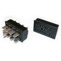
... DURA-CON Jones ® Plugs/Sockets High Reliability All-Plastic Series 300 300 Series with Hood and 180° Cable Clamp (CCT) No. of Catalog No. Contacts Plug 2 P-302-CCT 3 P-303-CCT 4 P-304-CCT 6 P-306-CCT 2 8 N/A 10 P-310-CCT 12 P-312-CCT 15 P-315-CCT 18 P-318-CCT 21 P-321-CCT 24 P-324-CCT 27 P-327-CCT 30 P-330-CCT 33 P-333-CCT Dimensions A ± .016 No ...
Page 44
... Jones [.050” (1.27mm) Density Plugs/Sockets Solder Cup/Wire Series 300 D-Microminiature] 300 Series Plug with Hood and Lock (CCT-L) and Socket with Hood and Keeper (CCT-K) No. of Catalog No. Catalog No. Contacts Plug w/ Lock Socket w/ Keeper 2 P-302-CCT-L S-302-CCT-K 3 P-303-CCT-L S-303-CCT-K 4 P-304-CCT-L S-304-CCT-K 6 P-306-CCT-L ...
Page 45
... Call Toll Free: 1 (800) 323-9612 [.050” (1.27mm) Density Multiple Density Solder Cup/Wire Solder Eyelet D-Microminiature] PLUGS ...
Page 46
... Polarized to prevent wrong-way insertion. ■ Plugs have projecting flat blades, sockets have recessed twin bellows. ■ Cable clamps of zinc and clear irridite-plated steel are used for strain relief. ■ Bifurcated bellows socket contact provides four individual flexing surfaces for maximum contact with the blade. ...
Page 47
... Series Less Angle Bracket No. of Catalog No. Catalog No. Contacts Plug 2 N/A S-2402-LAB 4 P-2404-LAB S-2404-LAB 6 P-2406-LAB S-2406-LAB 8 P-2408-LAB S-2408-LAB 10 P-2410-LAB S-2410-LAB 12 P-2412-LAB S-2412-LAB Plug Dimensions - Plug or Socket No. of Contacts 2 .563 4 1.000 6 1.438 8 1.875 10 2.313 12 2.750 Multiple Density Solder Eyelet Less Angle Bracket Socket Socket ...
Page 48
... M Contacts in 2 .563 4 1.000 6 1.438 8 1.875 10 2.313 12 2.750 Panel Cutout dimensions are on page 2-61. Call Toll Free: 1 (800) 323-9612 [.050” (1.27mm) Density Multiple Density Solder Cup/Wire Solder Eyelet D-Microminiature] With Angle Bracket Catalog No. Socket S-2402-AB S-2404-AB S-2406-AB S-2408-AB S-2410-AB S-2412-AB ...
Page 49
... Panel Cutout dimensions are on page 2-61. [.050” (1.27mm) Density Multiple Density Solder Cup/Wire Solder Eyelet D-Microminiature] Shallow Bracket Catalog No. Socket S-2402-SB S-2404-SB S-2406-SB S-2408-SB S-2410-SB S-2412- 1.062 26 ...
Page 50
... Panel Cutout dimensions are on page 2-61. Call Toll Free: 1 (800) 323-9612 [.050” (1.27mm) Density Multiple Density Solder Cup/Wire Solder Eyelet D-Microminiature] Deep Bracket Catalog No. Socket S-2402-DB S-2404-DB S-2406-DB S-2408-DB S-2410-DB ...
Page 51
... Jones [.050” (1.27mm) Density Plugs/Sockets Solder Cup/Wire Series 2400 D-Microminiature] 2400 Series with Hood and 90° Clamp No. of Catalog No. Catalog No. Contacts Plug 2 N/A S-2402-CCE 4 P-2404-CCE S-2404-CCE 6 P-2406-CCE S-2406-CCE 8 P-2408-CCE S-2408-CCE 10 P-2410-CCE S-2410-CCE 12 P-2412-CCE S-2412-CCE Dimensions - Plug or Socket No Contacts .625 15. ...
Page 52
... DURA-CON Jones ® Plugs/Sockets High Reliability Series 2400 All-Plastic 2400 Series with Hood and 180° Clamp No. of Catalog No. Contacts Plug 2 N/A 4 P-2404-CCT 6 P-2406-CCT 8 P-2408-CCT 2 10 P-2410-CCT 12 P-2412-CCT Plug Socket Dimensions - Plug or Socket No. of Contacts Call Toll Free: 1 (800) 323-9612 Multiple Density Solder Eyelet With Hood & ...
Page 53
... .938 23.81 1.438 36.51 1.375 34.93 1.438 36.51 1.813 46.04 1.438 36.51 2.250 57.15 1.438 36.51 2.688 68.28 1.438 36.51 3.125 79.38 1.438 36.51 2-57 Marketed exclusively through distribution. Call Toll Free: 1 (800) 323-9612 2 ...
Page 54
... Circular Mini DIN Plugs ■ Contact positions and 8. ■ Pre-assembled with standard shielded cable lengths; consult factory for other lengths. ■ Molded-in strain relief. ■ Cable and overmold available in standard colors: black or beige. ■ Contacts available with gold over nickel. ■ Shielding system designed to meet FCC requirements for EMI/RFI suppression. ...
Page 55
... The above cable assemblies are highly recommended for general commercial applications. Contact factory for other lengths or colors. For cable assemblies with plug on one end. Plug features contacts with Option 2 plating (Option 1 with additional gold in mating area). NOTE: Total gold thickness in mating area is 30 microinches. ...
Page 56
... Circular Mini DIN Plugs ■ Individual components available for cable assembly with overmolding. ■ Plug insulator available with contact positions and 8. ■ Seamless shield case is crimped to cable shield; designed to meet FCC requirements for EMI/RFI suppression. ■ One-piece shield case - no extra ferrules or shields required with Cinch Shield Crimp Tools. ■ ...
Page 57
... Prepare multi-conductor cable. • Crimp contacts onto individual conductors using tool MDT-P25 or tool MDT-P35. • Insert contact with conductor into insulator using tool MDT-P41 or have insertion tool MDT-P28 with insulator locating vice MDT-P29. • Insert insulator into the shield case using tool MDT-P34 or MDT-P30. ...
Page 58
... Dip solder tails on .200" (5.08mm) row centers double readout. ■ Bifurcated semi-bellows contacts for added contact reliability. ■ Ideal for applications involving vibration or board irregularities. ■ Contact positions: 12, 15, 18, 20, 22, 25, 28, 30, 31, 36, 37, 40, 43, 44, 49, 50, 52, 60, 70, AT, and XT. ■ Accepts .062" (1.59mm) thick PC boards. ...
Page 59
... Threaded Holes Catalog No. 50-12SN-13 50-15SN-13 50-18SN-13 - 50-20SN-13 50-22SN-13 50-25SN-13 50-28SN-13 50-30SN-13 50-31SN-13 - 50-36SN-13 50-37SN-13 50-40SN-13 50-43SN-13 50-44SN-13 50-49SN-13 50-50SN-13 50-52SN-13 50-60SN-13 50-70SN-13 Marketed exclusively through distribution. Call Toll Free: 1 (800) 323-9612 ...
Page 60
... CARDCON ™ Edge Connector Commercial ■ Dip solder tails single readout and double readout on .140" (3.56mm) row centers or .200" (5.08mm) row centers. ■ Solder eyelet, single readout and double readout on .200" (5.08mm) row centers. ■ Available with unique tails for PC board retention; holds the connector firmly on the board during wave soldering operations. ■ ...
Page 61
... Less Mounting Ears .128 Mounting Hole Pos./Cont. Catalog No. Catalog No. Dip solder tails, double readout, .140" (3.55mm) row spacing, .125" (3.18mm) long 6/12 50-12SN-4 50-12SN-2 10/20 50-20SN-4 50-20SN-2 12/24 50-24SN-4 50-24SN-2 15/30 ...
Page 62
... Edge Connector High Reliability ■ Dip solder tails, single readout, .156" (3.96mm) long or .234" (5.94mm) long. ■ Dip solder tails, double readout, .156" (3.96mm) or .234" (5.94mm) long on .200" (5.08mm) row spacing, or .125" (3.18mm) long on .140" (3.56mm) row spacing. ■ Solder eyelet, single readout and double readout on .200" (5.08mm) row spacing. ...
Page 63
... 1.785 45.34 2.410 61.21 2.723 69.16 3.191 81.05 3.660 92.96 3.973 100.91 4.285 108.84 4.754 120.75 Marketed exclusively through distribution. Call Toll Free: 1 (800) 323-9612 Call Toll Free: 1 (800) 323-9612 ...
Page 64
... Call Toll Free: 1 (800) 323-9612 [.050” (1.27mm) Density .156" (3.96mm) Density Dip Solder Cup/Wire Solder/Solder Eyelet D-Microminiature] .128" (3.25mm) Mounting Hole Dip Solder Tails Dip Solder Tails .156" (3.96mm) Long .234" (5.94mm) Long Catalog No ...
Page 65
... Accepts .062" (1.59mm) thick double-sided PC boards. Insulation Material: Diallyl phthalate, green Contact Material: Beryllium copper Contact Plating: 30µin. select gold over 50µin. nickel in the contact areas, 10µin. gold tails Shock: Per MIL-STD-202E, Method 213, Condition C Operating Temperature: -65°C to +125°C ...
Page 66
... Catalog No. 50-12S-30 50-20S-30 50-24S-30 50-30S-30 50-36S-30 50-44S-30 50-50S-30 2- 1.785 45.33 2.410 61.21 2.723 69.16 3.191 81.05 3.660 92.96 4.285 108.83 4.754 120.75 Marketed exclusively through distribution. Call Toll Free: 1 (800) 323-9612 ...
Page 67
... Edge Connector Accessories Card Guides Card guide for .100" (2.54mm) and .156" (3.96mm) density edge connectors. Accepts .062" (1.59mm) thick PC boards. Card guides attach to mounting ears and guide printed circuit board into connector. Order separately. Material: Polypropylene Part No. 50-GP-1 (Green) Part No. 50-GP-1B (Black) ...
Page 68
... Socket Commercial Miscellaneous Plug Buttons Nickel-plated steel. Spring tension prongs. 41V provides ventilation wherever required. Call Toll Free: 1 (800) 323-9612 Plug Buttons Dimensions For Hole Diameter in mm .250 6.35 .375 9.53 .500 12.70 .625 15.88 .750 19.05 .875 22.23 1.000 25.40 1 ...
Page 69
... Center Contact Insertion Force: < 2.0 lb.* Center Contact Removal Force: > 2.0 oz.* * Requirements are for two connector insertions into the same PC board mounting holes. PC board thickness can range from .093" to .300" thick. PC board hole requirements are as follows: Ground Legs: .059" Nom. Center Contact: .040" Nom. ...
Page 70
... Press-Fit BNC Coaxial Connector Board Mount Receptacle for 75 Ω Ω Applications Production Insertion Tool Design Press-Fit BNC Connector Dimensions Ordering Information Catalog Number: BNC-1-PF Standard Package: Anti-Static Tube, 48 Connectors Per Tube Call Toll Free: 1 (800) 323-9612 2-77 ...