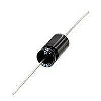
135D106X9050C6E3 Vishay, 135D106X9050C6E3 Datasheet

135D106X9050C6E3
Specifications of 135D106X9050C6E3
Related parts for 135D106X9050C6E3
135D106X9050C6E3 Summary of contents
Page 1
... High temperature film insulation rating. A decimal point codes is indicated by an “R” table High temperature (max. + 200 °C) (6R3 = 6 High temperature film insulation insulating sleeve tantalum@vishay.com standard tin/lead (SnPb), tantalum-case electrolytic 2 E3 STYLE NUMBER RoHS COMPLIANT E3 = 100 % tin ...
Page 2
... www.vishay.com 135D Vishay WEIGHT (g) (Max.) 2.6 6.2 11.6 17.7 MAX. RIPPLE 40 kHz I RMS (mA) 820 960 1200 1375 1800 1900 2265 820 900 1230 1370 1770 1825 2330 820 855 1200 1365 1720 1800 2360 ...
Page 3
... 125 ° 9.5 650 1.0 6.8 300 1.0 5.3 150 1.0 4.2 90 1.0 3.0 60 2.0 2.6 60 2.0 1.5 29 9.0 tantalum@vishay.com MAX. CAPACITANCE CHANGE (%) ° ° °C + 125 °C + 125 ° 200 ° 18.0 ...
Page 4
... www.vishay.com 135D Vishay MAX. RIPPLE 40 kHz I RMS (mA) 505 505 565 1240 835 965 1240 1335 1860 1800 415 520 755 860 1130 1200 1800 MAX. RIPPLE 40 kHz I RMS (mA) 1000 1500 1500 1900 1900 2300 1000 1500 1900 2300 900 ...
Page 5
... 125 ° 5.2 100 2 5.2 100 ° 125 ° ° 125 ° ° 125 ° 5.0 135 tantalum@vishay.com MAX. CAPACITANCE CHANGE (%) ° ° °C + 125 °C + 125 ° 200 ° 200 ° ...
Page 6
... 200 ° 200 ° www.vishay.com 135D Vishay MAX. RIPPLE 40 kHz I RMS (mA) 700 700 1100 1100 1400 1850 1850 715 700 1100 600 600 600 1100 1000 1000 1300 1800 2000 800 - 1300 - 1600 2000 - 700 1200 1200 1500 1850 1900 6 ...
Page 7
... Consult Vishay Sprague for information at + 200 °C. See paragraph 9. Working Voltage: The DC working voltage is the maximum operating voltage for continuous duty at the rated temperature. 3. Surge Voltage: The surge voltage rating is the maximum voltage to which the capacitors should be subjected ...
Page 8
... voltage shall not exceed 200 % of the original requirement or ± 10 µA, whichever is greater; the equivalent series resistance shall not be greater than 200 % of the original requirement; the capacitance value shall not increase by more than decrease by more than 20 % from the initial measurement. tantalum@vishay.com 1.0 0.9 0.8 0.7 0.6 ...
Page 9
... How to Order); rated DC working voltage at the standard EIA date code of manufacture. 21.1 Polarity shall be indicated by plus signs (+) adjacent to the positive terminal. For technical questions, contact: tantalum@vishay.com 135D Vishay [20.83 mm] of " be electrically effected insofar + 85 °C; www.vishay.com as 9 ...
Page 10
... I pp where: ESR = 4 Ω (from “Standard Ratings” table Therefore: and Therefore, the peak voltage of the capacitor is the limiting factor for the ripple current and can be calculated as follows: Max I or tantalum@vishay.com + (120 Hz) = 0.820 A x 0.6 = 0.492 A RMS × × ...
Page 11
... Vishay ambient 1M + 125 ° 0.32 + 125 ° 0.50 11 ...
Page 12
... Frequency in Hz www.vishay.com For technical questions, contact: 12 For example: For example: where DCL and 6. Special Applications: Vishay Sprague product specialists will, on request, furnish recommendations for your particular application. “C” Case 22 µ Capacitors (Extended Ratings) 100 ° ° °C 1 ° °C 0.1 ...
Page 13
... Document Number: 40024 Revision: 15-Nov-10 “F” Case 180 µ Capacitors (Extended Ratings) 100 ° ° °C 1 °C 0.1 1M 10M 100 For technical questions, contact: tantalum@vishay.com 135D Vishay - 55 ° ° ° °C + 125 ° °C 1K 10K 100K 1M Frequency in Hz www.vishay.com 10M 13 ...
Page 14
... Vishay product could result in personal injury or death. Customers using or selling Vishay products not expressly indicated for use in such applications their own risk and agree to fully indemnify and hold Vishay and its distributors harmless from and against any and all claims, liabilities, expenses and damages arising or resulting in connection with such use or sale, including attorneys fees, even if such claim alleges that Vishay or its distributor was negligent regarding the design or manufacture of the part ...


