SRF1280-681M Bourns Inc., SRF1280-681M Datasheet
SRF1280-681M
Manufacturer Part Number
SRF1280-681M
Description
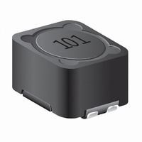
POWER INDUCTOR, 680UH, 760MA, 20%
Manufacturer
Bourns Inc.
Series
SRF1280r
Datasheet
1.SRF1280-100M.pdf
(2 pages)
Specifications of SRF1280-681M
Inductance Tolerance
± 20%
Dc Resistance Max
1.296ohm
Dc Current Rating
760mA
Core Material
Ferrite
Inductor Case Style
SMD
No. Of Pins
4
Inductance
680µH
Inductance Per Coil
680µH
Number Of Coils
2
Current
380mA
Tolerance
±20%
Inductance - Connected In Series
2.72mH
Inductance - Connected In Parallel
680µH
Dc Resistance (dcr)
2.444 Ohm Max
Package / Case
0.492" L x 0.492" W x 0.315" H (12.50mm x 12.50mm x 8.00mm)
Mounting Type
Surface Mount
Lead Free Status / RoHS Status
Lead free / RoHS Compliant
Other names
SRF1280-681MTR


*RoHS Directive 2002/95/EC Jan 27, 2003 including Annex.
Specifi cations are subject to change without notice.
Customers should verify actual device performance in their specifi c applications.
SRF1280-R47Y
SRF1280-1R0Y
SRF1280-1R5Y
SRF1280-2R2Y
SRF1280-3R3Y
SRF1280-4R7Y
SRF1280-6R8Y
SRF1280-8R2Y
SRF1280-100M
SRF1280-150M
SRF1280-220M
SRF1280-330M
SRF1280-470M
SRF1280-680M
SRF1280-820M
SRF1280-101M
SRF1280-151M
SRF1280-221M
SRF1280-331M
SRF1280-471M
SRF1280-681M
SRF1280-821M
SRF1280-102M
Bourns
Part No.
Electrical Specifi cations @ 25 °C
Recommended Layout
Electrical Schematic
1
3
N1
(.098)
REF.
2.50
REF.
(.020)
DUAL INDUCTOR MODE
0.50
Inductance
@ 100 KHz
L (μH)
1000
0.47
100
150
220
330
470
680
820
1.0
1.5
2.2
3.3
4.7
6.8
8.2
10
15
22
33
47
68
82
N2
3
2
4
2
1
4
±30
±30
±30
±30
±30
±30
±30
±30
±20
±20
±20
±20
±20
±20
±20
±20
±20
±20
±20
±20
±20
±20
±20
Tol.
(%)
Parallel Rating
1
3
(.543)
0.0055
0.0067
0.0076
0.0092
0.0135
0.0183
0.0191
0.0241
0.0333
0.0503
0.0664
0.0898
(.152)
13.80
REF.
3.85
0.011
0.123
0.153
0.175
0.261
0.343
0.865
1.296
1.632
1.992
N1
DCR
Max.
0.54
(Ω)
REF.
PARALLEL
Irms
17.9
15.5
13.5
12.5
10.4
8.25
7.34
6.32
6.04
5.03
3.23
2.95
2.44
2.09
1.96
1.59
1.29
1.04
0.85
0.76
0.65
0.61
(A)
4
N2
Features
■
■
■
■
■
SRF1280 Series - Dual-Winding Shielded Power Inductors
31.1
25.5
21.5
16.5
13.3
12.2
11.2
9.66
7.57
6.22
5.28
4.44
4.06
3.64
3.01
2.43
2.01
1.68
1.39
1.27
1.14
Isat
(A)
56
40
REF.
4
2
Multiple applications: parallel, series,
dual-inductor and transformer
Magnetically shielded, low radiation
Inductance range: 0.47 to 4000 μH
Rated current up to 17.9 A
RoHS compliant*
(.098)
(.020)
2.50
REF.
0.50
Inductance
@ 100 KHz
L (μH)
1320
1880
2720
3280
4000
1.88
13.2
18.8
27.2
32.8
132
188
272
328
400
600
880
SERIES MODE
8.8
40
60
88
3
2
4
6
1
1
4
3
N1
±30 0.0216
±30
±30 0.0306
±30 0.0338
±30
±30
±30 0.0656
±30 0.0714
±20 0.0921
±20
±20
±20
±20
±20
±20
±20
±20
±20
±20
±20
±20
±20
±20
Tol.
(%)
Series Rating
(.152)
SERIES
(.543)
3.85
13.80
REF.
0.026
0.129
0.192
0.265
0.353
0.469
0.578
0.701
1.013
2.172
4.888
5.896
7.202
DCR
Max.
0.04
0.05
1.38
(Ω)
3.3
REF.
N2
0.796
0.645
0.522
0.427 0.838
0.325 0.633
0.307 0.571
Irms
8.94
7.74
6.77
6.23
5.23
4.13
3.67
3.16
3.02
2.51
1.61
1.47
1.22
1.04
0.98
0.38
2
(A)
2
4
0.697
15.6
12.7
10.8
8.24
6.67
6.09
4.83
3.78
3.11
2.64
2.22
2.03
1.82
1.51
1.22
1.01
Isat
5.6
(A)
28
20
Applications
■
■
Test Voltage ..................................0.25 V
Hi-pot ................500 Vrms, 3 mA, 3 sec.
Refl ow Soldering .. 230 °C; 50 sec. max.
Operating Temperature
Storage Temperature .. -40 °C to +125 °C
Resistance to Solder Heat
Core ..............................................Ferrite
Wire ........................... Enameled copper
Base ................................................ LCP
Adhesive .............................. Epoxy resin
Terminal ................................... Cu/Ni/Sn
Rated Current
Temperature Rise .... 40 °C at rated Irms
Packaging .......400 pcs. per 13-inch reel
Model
Value Code (see table)
SEPIC topology
Power supplies for:
(.299 ± .008)
General Specifi cations
Materials
Product Dimensions
How to Order
................................. -40 °C to +105 °C
...............................+260 °C for 10 sec.
........... Inductance drops 30 % at Isat
7.60 ± 0.2
- Communication equipment
- Notebooks, desktop computers,
- LCDs, fl at panels, backlights
- Camcorders, HDTVs, car audio
servers
systems
DIMENSIONS:
(Temperature rise included)
(.492)
12.50
1
4
MAX.
2
3
SRF1280 - 100M
(INCHES)
(.071 ± .008)
(.197 ± .012)
1.80 ± 0.2
5.00 ± 0.3
MM
(.492)
12.50
MAX.
(.315)
8.00
MAX.
Related parts for SRF1280-681M
Image
Part Number
Description
Manufacturer
Datasheet
Request
R


Part Number:
Description:
POWER INDUCTOR, 100UH, 1.96A, 20%
Manufacturer:
Bourns Inc.
Datasheet:
Part Number:
Description:
POWER INDUCTOR, 1MH, 610MA, 20%
Manufacturer:
Bourns Inc.
Datasheet:

Part Number:
Description:
Manufacturer:
Bourns, Inc.
Datasheet:
Part Number:
Description:
11mm Potentiometer
Manufacturer:
Bourns, Inc.
Datasheet:
SRF1280-681M Summary of contents
Page 1
... SRF1280-820M 82 ±20 0.153 SRF1280-101M 100 ±20 0.175 SRF1280-151M 150 ±20 0.261 SRF1280-221M 220 ±20 0.343 SRF1280-331M 330 ±20 0.54 SRF1280-471M 470 ±20 0.865 SRF1280-681M 680 ±20 1.296 SRF1280-821M 820 ±20 1.632 SRF1280-102M 1000 ±20 1.992 Electrical Schematic PARALLEL Recommended Layout 2.50 3 ...
Page 2
... SRF0504 Series - Line Filter SRF1280 Series - Dual-Winding Shielded Power Inductors Packaging Specifi cations 330 2.0 ± 0.5 DIA. (12.99) (.079 ± .020) 21.0 ± 0.8 (.827 ± .031) 13.0 DIA. (.512) END NO COMPONENT 200 (7.87) Asia-Pacifi c: Tel: +886-2 2562-4117 • Fax: +886-2 2562-4116 Europe: Tel: +41-41 768 5555 • ...