PM1812-561J Bourns Inc., PM1812-561J Datasheet

SMD INDUCTOR, 560UH, 50MA, 5%, 2MHZ

PM1812-561J

Manufacturer Part Number
PM1812-561J
Description
SMD INDUCTOR, 560UH, 50MA, 5%, 2MHZ
Manufacturer
Bourns Inc.
Datasheet

Specifications of PM1812-561J

Inductance Tolerance
± 5%
Dc Resistance Max
30ohm
Dc Current Rating
50mA
Self Resonant Frequency
2MHz
Q Factor
30
Core Material
Ferrite
Inductor Case Style
1812
Inductance
560µH
Lead Free Status / RoHS Status
Contains lead / RoHS non-compliant
Temperature Rise .......................................................................................................................................................................20 ˚C max.
Ambient Temperature ................................................................................................................................................................ 80 ˚C max.
Operating Temperature ................................................................................................................................................... -40 °C to +100 °C
Storage Temperature ...................................................................................................................................................... -40 °C to +100 °C
Resistance to Soldering Heat
Ferrite Core
Coil Type .................................................................................................................................................................................. Copper wire
Enclosure .................................................................................................................................................................................. Epoxy resin
Terminal ...................................................................................................................................................................................................Sn
*RoHS Directive 2002/95/EC Jan 27 2003 including Annex.
Specifi cations are subject to change without notice.
Customers should verify actual device performance in their specifi c applications.
General Specifi cations
Materials
PM1210 .......................................................................................................................................................................260 ˚C, 5 seconds
PM1812 .......................................................................................................................................................................245 ˚C, 5 seconds
PM1210 ................................................................................................................................................................................................ All
PM1812 ................................................................................................................................................................................................ All
Product Dimensions
Recommended Land Pattern Dimensions
c
PM1210
a
b
Marking
(.126)
(.079)
3.2
2.5
(.086)
(.024)
2.2
0.6
Features
PM1210 & PM1812 Series SMT Chip Inductors
Model
PM1210
PM1812
Formerly
High resistance to heat and humidity
Resistance to mechanical shock and
pressure
Accurate dimensions for automatic
surface mounting
Wide inductance range (1.0 nH to 1000 µH)
RoHS compliant*
(.075)
1.9
J. W .Miller
model
(.063 to .079)
(.094 to .102)
1.6 to 2.0
2.4 to 2.6
(.039)
1.0
a
PM1812
DIMENSIONS:
Applications
(INCHES)
Marking
(.157 to .181)
(.217 to .236)
(.177)
MM
DC/DC converters
Power supplies
General use
4.5
(.125)
4.0 to 4.6
5.5 to 6.0
3.2
(.039)
1.0
(.125 ± .008)
b
3.2 ± 0.2
(.066 ± .008)
1.7 ± 0.2
(.047)
1.2
(.075 to .094)
(.079 to .118)
1.9 to 2.4
2.0 to 3.0
c

Related parts for PM1812-561J

PM1812-561J Summary of contents

Page 1

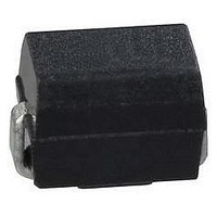
... High resistance to heat and humidity ■ Resistance to mechanical shock and pressure ■ Accurate dimensions for automatic surface mounting ■ Wide inductance range (1 1000 µH) ■ RoHS compliant* PM1210 & PM1812 Series SMT Chip Inductors PM1812 1.9 (.075) 1.0 (.039) Model a 1.6 to 2.0 PM1210 (.063 to .079) 2 ...

Page 2

... PM1210 & PM1812 Series SMT Chip Inductors Packaging Specifi cations PM1210 Series Ø DIA Chip P1 Component Tape running direction Model 2.80 3.60 8.00 PM1210 (.110) (.142) (.315) 3.60 4.90 12.00 PM1812 (.142) (.193) (.472) Reel Dimensions Model A B 178 PM1210 60 min ...

Page 3

... PM1210 & PM1812 Series SMT Chip Inductors PM1210 Series RoHS Complliant 1210 Size Inductance Part Number µH Tolerance PM1210-1R0J-RC 1.0 PM1210-1R2J-RC 1.2 PM1210-1R5J-RC 1.5 PM1210-1R8J-RC 1.8 PM1210-2R2J-RC 2.2 PM1210-2R7J-RC 2.7 PM1210-3R3J-RC 3.3 PM1210-3R9J-RC 3.9 PM1210-4R7J-RC 4.7 PM1210-5R6J-RC 5.6 PM1210-6R8J-RC 6.8 PM1210-8R2J-RC 8 ...

Page 4

... PM1812-181J-RC 180 PM1812-221J-RC 220 PM1812-271J-RC 270 PM1812-331J-RC 330 PM1812-391J-RC 390 PM1812-471J-RC 470 PM1812-561J-RC 560 PM1812-681J-RC 680 PM1812-821J-RC 820 PM1812-102J-RC 1000 REV. 07/10 Specifi cations are subject to change without notice. Customers should verify actual device performance in their specifi c applications. Q µH Tolerance min ...

Related keywords