Taper .................................... Linear, audio
Standard Resistance Range
Standard Resistance Tolerance .....±20 %
Residual Resistance ................. 1 % max.
Operating Temperature
Power Rating ............................ 0.05 Watt
Maximum Operating Voltage
Sliding Noise ...................... 100 mV max.
Mechanical Angle .....................300 ° ±5 °
Rotational Torque ............20 to 200 g-cm
Detent Torque ..................30 to 300 g-cm
Stop Strength
Rotational Life ................... 15,000 cycles
Soldering Condition
Hardware ................. One fl at washer and
MODEL PTT 111
MODEL PTV 111
MODEL PTV 112
Electrical Characteristics
Environmental Characteristics
Mechanical Characteristics
Electrical Diagrams
no bushing .................... 3 kg-cm min.
with bushing .................. 3 kg-cm min.
....................... 1 K ohms to 1 M ohms
.................................-10 °C to +50 °C
............................... 50 V AC, 20 V DC
............300 °C max. within 3 seconds
2
1
1
potentiometer with bushing
1
mounting nut supplied per
2
1
2
2
3
3
3
4
4
3
DUMMY
Features
■
■
■
■
■
■
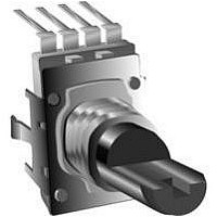
PTV/PTT Series - 12 mm Potentiometer
RECOMMENDED PCB LAYOUT
PTV111-2
DIA. HOLES 4 PLCS.
(.137)
(.102)
F
L
3.5
2.6
Carbon element
Insulated shaft
Snap-in clip
Center detent
Center tap option
Assorted pin layouts
Product Dimensions
(.082
Dimensions Without Bushing
(.393)
(.039
10.0
2.1
(.031
1.0
(.591)
(.177)
4.5
+0.003
15
0.8
+0.1
-0.0
+0.007
-0.0
+0.2
-0.0
-0.0
+0.003
-0.003
+0.1
-0.1
SHAFT SHOWN IN CCW POSITION
)
)
(.433)
(.472)
11.0
12.0
)
(.787)
(.276)
(.078)
(.318)
2.0
1
20
8.1
7
2
(.295)
(.401)
(.240)
7.5
10.2
(.886)
(.276)
6.1
22.5
(.157)
L
3
7
4.0
(.062)
1.6
30 °
4
(.059)
1.5
(.984)
(.472)
(.263)
(.098)
25
12
(.177
F
6.7
2.5
Customers should verify actual device performance in their specifi c applications.
(.370)
(.019)
(.236
9.4
0.5
(.078
4.5
-0.019
6.0
2.0
+0
-0.019
-0.5
+0
(.129)
(1.083)
+0
+0.003
-0.5
(.472)
3.3
)
+0
+0.1
-0.0
-0.0
27.5
12
)
(.019)
0.5
)
■
■
*RoHS Directive 2002/95/EC Jan 27 2003 including Annex
RECOMMENDED PCB LAYOUT
PTV111-4
Dual gang option
Various taper options
DIA. HOLES 4 PLCS.
(.082
(.078 ± .005)
(.433)
(.433)
(.472)
11.0
2.1
11.0
2.0 ± 0.15
(.393)
12.0
(.039
Specifi cations are subject to change without notice.
10.0
+0.003
1.0
+0.1
-0.0
-0.0
+0.007
+0.2
-0.0
-0.0
)
)
SHAFT SHOWN IN CCW POSITION
DIMENSIONS:
(.150)
(.137)
(.334)
3.8
3.5
1
8.5
30 °
2
(.295)
(.535)
7.5
13.6
(.263)
6.7
3
L
(INCHES)
4
MM
(.031
(.059)
1.5
0.8
TERMINAL DETAIL
(.098)
2.5
(.177
F
+0.003
(.433)
-0.003
11.0
+0.1
(.019)
(.236
-0.1
0.5
4.5
(.078
-0.019
6.0
)
2.0
+0
-0.019
-0.5
+0
+0
-0.5
+0.003
)
+0
-0.0
-0.0
(.019)
)
0.5
)