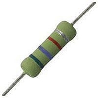
PTF56250R00BYEK Vishay, PTF56250R00BYEK Datasheet - Page 3

PTF56250R00BYEK
Manufacturer Part Number
PTF56250R00BYEK
Description
RESISTOR, METAL FILM, 250OHM, 125mW, 0.1%
Manufacturer
Vishay
Series
PTFr
Type
Metal Film Resistors, High Precision, High Stabilityr
Datasheet
1.PTF5645R300FYEB.pdf
(4 pages)
Specifications of PTF56250R00BYEK
Resistance
250ohm
Resistance Tolerance
± 0.1%
Power Rating
125mW
Voltage Rating
300V
Resistor Element Material
Metal Film
Temperature Coefficient
± 10ppm/°C
Tolerance
0.1 %
Termination Style
Axial
Operating Temperature Range
- 55 C to + 150 C
Dimensions
2.31 mm Dia. x 6.35 mm L
Lead Free Status / RoHS Status
Lead free / RoHS Compliant
www.vishay.com
88
PTF
Vishay Dale
LOAD LIFE SHIFT DUE TO POWER AND DERATING (AT 85 °C)
The power rating for the PTF parts is tied to the derating temperature, the heat rise of the parts, and the ΔR for the load life performance.
When the tables/graphs below are used together they show that when the parts are run at higher power ratings, the parts will run hotter,
which has the potential of causing the resistance of the parts to shift more over the life of the part.
Example: When a PTF56 part is run at 1/8 W in a 70 °C ambient environment, the resistor will generate enough heat that the surface
temperature of the part will reach about 17 °C over the ambient temperature, and over the life of the part this could cause the resistance
value to shift up to ± 0.04 %.
If the same resistor was instead run at 1/4 W in a 70 °C environment, the element will heat up to about 30 °C over ambient, and over the life
of the part the resistance value could shift roughly ± 0.5 %.
And if the resistor was run at its maximum power rating of 1/2 W in a 70 °C environment, it will heat up to about 61°C over ambient, and you
could see the resistance value shift roughly ± 1 % over the life of the part.
TEMPERATURE COEFFICIENT OF RESISTANCE
Temperature coefficient (TC) of resistance is normally stated as the maximum amount of resistance change from the original + 25 °C value
as the ambient temperature increases or decreases. This is most commonly expressed in parts per million per degree centigrade (ppm/°C).
The resistance curve over the operating temperature range is usually a non-linear curve within predictable maximum limits. PTF resistors
have a very unifom resistance temperature characteristic when measured over the operating range of - 20 °C to + 85 °C. The standard
temperature coefficients available are
X = ± 15 ppm/°C, Y = ± 10 ppm/°C and Z = ± 5 ppm/°C.
Some applications of the PTF require operation beyond the specifications of - 20 °C to + 85 °C. The change in temperature coefficient of
resistance is very small (less than ± 0.05 ppm/°C) over the expanded temperature range of - 55 °C to + 150 °C. Therefore, when operating
outside the range - 20 °C to + 85 °C, the designer can plan for a worst case addition of ± 0.05 ppm/°C for each degree centigrade beyond
either - 20 °C or + 85 °C as indicated in the graph. This applies to all three temperature coefficient codes.
Example: Assume the operating characteristics demand a temperature range from - 55 °C to + 125 °C. This requires a ± 35 °C Δ below
- 20 °C and a ± 40 °C Δ above + 85 °C. The extreme Δ being ± 40 °C means that the worst case addition to the specified TC limit of
± 0.05 ppm/°C times ± 40 °C or ± 2 ppm/°C. Therefore, a Z which is characterized by a base TC limit of ± 5 ppm/°C over the temperature
range of - 20 °C to + 85 °C will exhibit a maximum temperature coefficient of ± 7 ppm/°C over the expanded portion of the temperature
range of - 55 °C to + 125 °C.
DERATING
LOAD LIFE SHIFT VS. POWER RATING
LOAD LIFE
MODEL
PTF51
PTF56
PTF65
100
120
60
80
40
20
- 55
0
- 25
MIL-PRF-55182 Paragraph 4.8.18
0
1000 h rated power at + 85 °C
CONDITIONS OF TEST
25
50
Metal Film Resistors, High Precision, High Stability
AMBIENT TEMPERATURE IN °C
75
85
For technical questions, contact:
100
3
2
1
0
4
125
- 50 - 40 - 30 - 20
OPERATING RANGE
- 55 °C TO - 20 °C
150
EXPANDED
175
≤ ± 0.04 %
1/20 W
1/8 W
1/4 W
200
- 20 °C TO + 85 °C
BASE TC LIMIT
X, Y
or Z
THERMAL RESISTANCE
ff2aresistors@vishay.com
120
100
80
60
40
20
0
MAXIMUM ΔR (TYPICAL TEST LOTS)
0
90 100 110 120 130 140 150
≤ ± 0.15 %
1/10 W
POWER RATING AT + 85 °C
0.125
-
-
OPERATING RANGE
- 85 °C TO + 150 ° C
EXPANDED
0.25
0.375
≤ ± 0.5 %
0.5
1/8 W
1/4 W
1/2 W
0.625
PTF51
APPLIED POWER IN W
Document Number: 31019
0.75 0.875
Revision: 18-Nov-10
≤ ± 1.0 %
1/4 W
1/2 W
3/4 W
PTF56
PTF65
1
1.125


