TA310PA250RJE Ohmite, TA310PA250RJE Datasheet
TA310PA250RJE
Manufacturer Part Number
TA310PA250RJE
Description
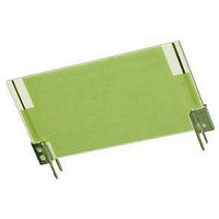
RESISTOR, THICK FILM, 250OHM, 10W, 5%
Manufacturer
Ohmite
Series
Power Chipr
Datasheet
1.TA205PA33R0J.pdf
(1 pages)
Specifications of TA310PA250RJE
Resistance
250ohm
Resistance Tolerance
± 5%
Power Rating
10W
Resistor Element Material
Thick Film
Resistor Case Style
Radial Leaded
No. Of Pins
2
Lead Free Status / RoHS Status
Lead free / RoHS Compliant
TA Series
Power Chip
Thick Film on Alumina Substrate
54
10.00 –––10ROJ
11.00 –––11R0J
12.00 –––12R0J
15.00 –––15R0J
20.00 –––20R0J
24.00 –––24R0J
27.00 –––27R0J
33.00 –––33R0J
47.00 –––47R0J
= Most popular standard values, = Stock values, =
0.25 –––R250J
1.00 –––1R00J
1.50 –––1R50J
2.00 –––2R00J
4.70 –––4R70J
5.00 –––5R00J
5.10 –––5R10J
7.50 –––7R50J
8.20 –––8R20J
TA303
TA605
TA310
TA810
TA203
TA205
TA305
TA805
TA207
TA307
TA025
TA050
TA100
Series
Ohmite Mfg. Co.
3, 5, 7.5
& 10 watt
10, 25, 50
& 100 watt
0.150" / 3.8 mm ref.
Part No.
Prefix
Suffix
typical
PC board
Wattage
0.07"/1.78mm
100.0
10.0
10.0
25.0
50.0
3.0
3.0
5.0
5.0
5.0
5.0
7.5
7.5
®
H
0.050" / 1.27 mm dia. finished pins
H
1600 Golf Rd., Rolling Meadows, IL 60008 • 1-866-9-OHMITE • Int’l 1-847-258-0300 • Fax 1-847-574-7522 • www.ohmite.com • info@ohmite.com
0.02" x 0.015" Pins
0.600 / 15.24
0.800 / 20.32
0.800 / 20.32
0.200 / 5.08
0.300 / 7.62
0.200 / 5.08
0.300 / 7.62
0.200 / 5.08
0.300 / 7.62
0.300 / 7.62
4.10 / 104.1
Part Number
1.90 / 48.3
1.90 / 48.3
0.020" / 0.51 mm typ.
0.200" / 5.08 mm
P
P
L
Dimensions (±.020 in. / ±.508mm)
L
P
4.420 / 112.27
2.220 / 56.39
2.220 / 56.39
0.50 / 12.70
0.50 / 12.70
0.50 / 12.70
0.50 / 12.70
1.00 / 25.40
1.00 / 25.40
0.75 / 19.05
0.75 / 19.05
1.00 / 25.40
1.00 / 25.40
0. 1 0"/2.54mm
Length L
S t a n d a r d p a r t n u m b e r S f o r t a S e r i e S
0.070" /
1.78 mm
1,000.00 –––1K00J
1,500.00 –––1K50J
1,800.00 –––1K80J
2,000.00 –––2K00J
6.10 mm
0.17"/4.32mm
0.240" /
100.00 –––100RJ
150.00 –––150RJ
200.00 –––200RJ
250.00 –––250RJ
270.00 –––270RJ
300.00 –––300RJ
470.00 –––470RJ
500.00 –––560
620.00 –––620RJ
680.00 –––680RJ
50.00 –––50R0J
62.00 –––62R0J
68.00 –––68R0J
75.00 –––75R0J
Solder-coated
phosphor bronze
0.040" / 1.02 mm
1.02 mm typ.
1.170 / 29.70
2.270 / 57.60
2.270 / 57.60
0.60 / 15.24
0.60 / 15.24
1.00 / 25.40
1.00 / 25.40
0.50 / 12.70
0.50 / 12.70
1.00 / 25.40
1.00 / 25.40
1.00 / 25.40
1.00 / 25.40
0.040" /
Part No.
Prefix
Suffix
Height H
Non-standard values subject to minimum handling charge per item
0.300" /
7.62 mm
Part Number
Ohmite’s original Power Chip
resistors feature our thick film
on alumina substrate technol-
ogy. These planar packages
yield space saving, 10W/in
power densities that require
over 50% less board space
than other radial packages.
Convection cooling is maxi-
mized by the planar package
configuration which dissipates
heat well above board level.
tors have a 125% higher oper-
ating temperature range than
competitive product of similar
design. High temperature
solder and in-process plat-
ing keep terminations secure
under self-heating effects by
preventing re-flow from full
power operation.
make these resistors ideal for
power supplies, audio ampli-
fiers, video fly-back, and other
power control applications.
F e A T u r e S
• High-Temp Terminal Construction
• Wide Resistance Range
• Low Inductance (50nH-100nH)
• High Power Density
• Easy to install. PC-mountable
Ohmite’s power chip resis-
Flexible packaging schemes
Series
T A
Power Rating:
025 = 25
050 = 50
100 = 100
03 = 3 W
05 = 5
07 = 7.5
10 = 10
3
Pin spacing
(on 3-10W models only)
2 = .2"
3 = .3"
8 = .8"
0 5 P A 4 K 5 0 J
o r d e r i n G i n f o r m a t i o n
2,500.00 –––2K50J
3,000.00 –––3K00J
4,000.00 –––4K00J
4,700.00 –––4K70J
5,000.00 –––5K00J
5,100.00 –––5K10J
7,500.00 –––7K50J
10,000.00 –––10K0J
15,000.00 –––15K0J
18,000.00 –––18K0J
20,000.00 –––20K0J
30,000.00 –––30K0J
39,000.00 –––39K0J
50,000.00 –––50K0J
75,000.00 –––75K0J
100,000
150,000
200,000
Check product availability at
Package:
PA = pin terminals,
std. for 3-10 W
PW = wraparound,
std. for 10-100 W
2
–––100KJ
–––150KJ
–––200KJ
Part No.
Prefix
Suffix
Tolerance
K = 10%
J = 5%
F = 1%
S P e C i F i C A T i O N S
Material
Substrate: Alumina
Resistor: Thick Film
Coating: Glass
Terminals: Solder Plated
Thermal Conductivity:
Temperature Coefficient:
Electrical
Tolerance: ±1%, ±5% and ±10%
Power Rating: Based on 25°C
Resistance Range: 0.25 ohm to
Maximum Operating Voltage:
Overload: Five times rated power,
Derating:
Phosphor Bronze
20 Watts/Meter/°C
1 ohm
1 to 100Ω
101Ω and up
free air
10M ohm. Consult factory for
other values
350 VAC, 500 VDC through
glass, 1000 VAC, 1500 VDC
through substrate
as long as the one second aver-
age dissipation does not exceed
the wattage rating.
∆R: ±2%, 2000 hours
100% @ 25°C to 0% @ 180°C
ambient.
Resistance Value (Ω)
R250 = 0.25
10R0 = 10.0
2K00 = 2,000
45K0 = 45,000
RoHS compliant
E
Part Number
www.ohmite.com
450 ppm/°C
100 ppm/°C
50 ppm/°C
Related parts for TA310PA250RJE
Image
Part Number
Description
Manufacturer
Datasheet
Request
R

Part Number:
Description:
RESISTOR POWER 1.0 OHM 50W
Manufacturer:
Ohmite
Datasheet:

Part Number:
Description:
POINTER BAR KNOB, 6.35MM
Manufacturer:
Ohmite
Datasheet:

Part Number:
Description:
HAND WHEEL POINTER KNOB, 9.525MM
Manufacturer:
Ohmite
Datasheet:

Part Number:
Description:
FINGER GRIP KNOB, 3.175MM
Manufacturer:
Ohmite
Datasheet:


Part Number:
Description:
MOUNTING CLIP, 90 SERIES RESISTOR
Manufacturer:
Ohmite
Datasheet:

Part Number:
Description:
ADJUSTABLE LUG FOR DIVIDOHM
Manufacturer:
Ohmite
Datasheet:
Part Number:
Description:
ADJUSTABLE LUG FOR DIVIDOHM
Manufacturer:
Ohmite
Datasheet:


Part Number:
Description:
Tact switch 6x6mm, Stem H: 4.35mm, White , 185+/-50gf
Manufacturer:
Diptronics
Part Number:
Description:
RESISTOR POWER 1.0 OHM 50W
Manufacturer:
Ohmite
Datasheet:
Part Number:
Description:
HAND WHEEL POINTER KNOB, 9.525MM
Manufacturer:
Ohmite
Datasheet: