CW02B250R0JE12 Vishay, CW02B250R0JE12 Datasheet - Page 2
CW02B250R0JE12
Manufacturer Part Number
CW02B250R0JE12
Description
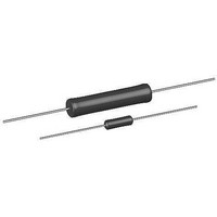
RESISTOR, WIREWOUND, 250OHM, 3W, 5%
Manufacturer
Vishay
Series
CWr
Datasheet
1.CW0058R000JE73.pdf
(3 pages)
Specifications of CW02B250R0JE12
Resistance
250ohm
Resistance Tolerance
± 5%
Power Rating
3W
Resistor Element Material
Wirewound
Resistor Case Style
Axial Leaded
No. Of Pins
2
Temperature Coefficient
± 30ppm/°C
Tolerance
5 %
Termination Style
Axial
Operating Temperature Range
- 65 C to + 250 C
Dimensions
4.78 mm Dia. x 15.8 mm L
Product
Power Resistors Wire Wound Silicon Coated
Dielectric Strength
1000 Volts
Lead Free Status / RoHS Status
Lead free / RoHS Compliant


DIMENSIONS in inches (millimeters)
Notes
(1)
(2)
MATERIAL SPECIFICATIONS
Element: Copper-nickel alloy or nickel-chrome alloy,
depending on resistance value
Core: Ceramic: Steatite or alumina, depending on physical
size
Coating: Special high temperature silicone
Standard Terminals: Tinned Copperweld
End Caps: Stainless steel
Part Marking: DALE, model, wattage
date code
Note
(3)
Note
(4)
document number: 30215
Revision: 19-Oct-10
MODEL
CW1/2
CW001
CW01M
CW002
CW02M
CW02B
CW02B...13
CW02C
CW02C...14
CW005
CW005...2
CW005...3
CW007
CW010
CW010...3
PERFORMANCE
TEST
Thermal Shock
Short Time Overload
Dielectric Withstanding Voltage
Low Temperature Storage
High Temperature Exposure
Moisture Resistance
Shock, Specified Pulse
Vibration, High Frequency
Load Life
Terminal Strength
On some standard reel pack methods, the leads may be trimmed to a shorter length than shown
B (maximum) dimension is clean lead to clean lead
Wattage marked on resistor will be “V” characteristic, CW1/2 will
not be marked with wattage
All ΔR figures shown are maximum, based upon testing requirements per MIL-PRF-26 at a maximum operating temperature of + 350 °C.
ΔR maximum figures are considerably lower when tested at a maximum operating temperature of + 250 °C.
0.406 ± 0.031 (10.31 ± 0.787)
0.250 ± 0.031 (6.35 ± 0.787)
0.285 ± 0.025 (7.24 ± 0.635)
0.625 ± 0.062 (15.87 ± 1.57)
0.500 ± 0.062 (12.70 ± 1.57)
0.562 ± 0.062 (14.27 ± 1.57)
0.500 ± 0.062 (12.70 ± 1.57)
0.500 ± 0.062 (12.70 ± 1.57)
0.500 ± 0.062 (12.70 ± 1.57)
0.875 ± 0.062 (22.22 ± 1.57)
0.875 ± 0.062 (22.22 ± 1.57)
0.875 ± 0.062 (22.22 ± 1.57)
1.218 ± 0.062 (30.94 ± 1.57)
1.781 ± 0.062 (45.24 ± 1.57)
1.781 ± 0.062 (45.24 ± 1.57)
(4)
Wirewound Resistors, Commercial Coated, Axial Lead
A
Rated power applied until thermally stable, then a minimum of 15 min at - 55 °C
5 x rated power (3.75 W and smaller), 10 x rated power (4 W and larger) for 5 s
1000 V
- 65 °C for 24 h
250 h at + 350 °C
MIL-STD-202 Method 106, 7b not applicable
MIL-STD-202 Method 213, 100 g’s for 6 ms, 10 shocks
Frequency varied 10 Hz to 2000 Hz, 20 g peak, 2 directions 6 h each
2000 h at rated power, + 25 °C, 1.5 h “ON”, 0.5 h “OFF”
5 s to 10 s 10 pound pull test; torsion test - 3 alternating directions, 360 °C each
For technical questions, contact:
rms
(3)
, 1 min
, value, tolerance,
®
1.50 (38.10)
minimum
B (maximum)
0.437 (11.10)
0.765 (19.43)
0.562 (14.27)
0.622 (15.80)
0.563 (14.30)
0.593 (15.06)
0.593 (15.06)
1.281 (32.54)
1.875 (47.62)
1.875 (47.62)
0.281 (7.14)
0.311 (7.90)
1.0 (25.40)
1.0 (25.40)
1.0 (25.40)
(1)
DIMENSIONS in inches (millimeters)
CONDITIONS OF TEST
(2)
B
A
ww2aresistors@vishay.com
0.085 ± 0.020 (2.16 ± 0.508)
0.094 ± 0.031 (2.39 ± 0.787)
0.110 ± 0.015 (2.79 ± 0.381)
0.250 ± 0.032 (6.35 ± 0.813)
0.185 ± 0.015 (4.70 ± 0.381)
0.188 ± 0.032 (4.78 ± 0.813)
0.188 ± 0.032 (4.78 ± 0.813)
0.218 ± 0.032 (5.54 ± 0.813)
0.218 ± 0.032 (5.54 ± 0.813)
0.312 ± 0.032 (7.92 ± 0.813)
0.250 ± 0.032 (6.35 ± 0.813)
0.312 ± 0.032 (7.92 ± 0.813)
0.312 ± 0.032 (7.92 ± 0.813)
0.375 ± 0.032 (9.52 ± 0.813)
0.375 ± 0.032 (9.52 ± 0.813)
Derating
120
100
80
60
40
20
0
- 65
C
- 50
C
D
0
25
50
CHAR. U
0.020 ± 0.002 (0.508 ± 0.051)
0.020 ± 0.002 (0.508 ± 0.051)
0.020 ± 0.002 (0.508 ± 0.051)
0.032 ± 0.002 (0.813 ± 0.051)
0.032 ± 0.002 (0.813 ± 0.051)
0.032 ± 0.002 (0.813 ± 0.051)
0.032 ± 0.002 (0.813 ± 0.051)
0.032 ± 0.002 (0.813 ± 0.051)
0.032 ± 0.002 (0.813 ± 0.051)
0.032 ± 0.002 (0.813 ± 0.051)
150
AMBIENT TEMPERATURE IN °C
0.040 ± 0.002 (1.02 ± 0.051)
0.040 ± 0.002 (1.02 ± 0.051)
0.040 ± 0.002 (1.02 ± 0.051)
0.040 ± 0.002 (1.02 ± 0.051)
0.040 ± 0.002 (1.02 ± 0.051)
CHAR. V
(CHARACTERISTIC V)
± (2.0 % + 0.05 Ω) ΔR
± (2.0 % + 0.05 Ω) ΔR
± (0.1 % + 0.05 Ω) ΔR
± (2.0 % + 0.05 Ω) ΔR
± (4.0 % + 0.05 Ω) ΔR
± (2.0 % + 0.05 Ω) ΔR
± (0.2 % + 0.05 Ω) ΔR
± (0.2 % + 0.05 Ω) ΔR
± (3.0 % + 0.05 Ω) ΔR
± (1.0 % + 0.05 Ω) ΔR
Vishay Dale
TEST LIMITS
250
D
www.vishay.com
CW
350
21
Related parts for CW02B250R0JE12
Image
Part Number
Description
Manufacturer
Datasheet
Request
R

Part Number:
Description:
357-036-542-201 CARDEDGE 36POS DL .156 BLK LOPRO
Manufacturer:
Vishay
Datasheet:
Part Number:
Description:
357-036-542-201 CARDEDGE 36POS DL .156 BLK LOPRO
Manufacturer:
Vishay
Datasheet:
Part Number:
Description:
357-036-542-201 CARDEDGE 36POS DL .156 BLK LOPRO
Manufacturer:
Vishay
Datasheet:
Part Number:
Description:
357-036-542-201 CARDEDGE 36POS DL .156 BLK LOPRO
Manufacturer:
Vishay
Datasheet:
Part Number:
Description:
357-036-542-201 CARDEDGE 36POS DL .156 BLK LOPRO
Manufacturer:
Vishay
Datasheet:
Part Number:
Description:
357-036-542-201 CARDEDGE 36POS DL .156 BLK LOPRO
Manufacturer:
Vishay
Datasheet:
Part Number:
Description:
357-036-542-201 CARDEDGE 36POS DL .156 BLK LOPRO
Manufacturer:
Vishay
Datasheet:
Part Number:
Description:
357-036-542-201 CARDEDGE 36POS DL .156 BLK LOPRO
Manufacturer:
Vishay
Datasheet:
Part Number:
Description:
357-036-542-201 CARDEDGE 36POS DL .156 BLK LOPRO
Manufacturer:
Vishay
Datasheet:
Part Number:
Description:
357-036-542-201 CARDEDGE 36POS DL .156 BLK LOPRO
Manufacturer:
Vishay
Datasheet:
Part Number:
Description:
357-036-542-201 CARDEDGE 36POS DL .156 BLK LOPRO
Manufacturer:
Vishay
Datasheet:
Part Number:
Description:
357-036-542-201 CARDEDGE 36POS DL .156 BLK LOPRO
Manufacturer:
Vishay
Datasheet:
Part Number:
Description:
357-036-542-201 CARDEDGE 36POS DL .156 BLK LOPRO
Manufacturer:
Vishay
Datasheet:
Part Number:
Description:
357-036-542-201 CARDEDGE 36POS DL .156 BLK LOPRO
Manufacturer:
Vishay
Datasheet:
Part Number:
Description:
357-036-542-201 CARDEDGE 36POS DL .156 BLK LOPRO
Manufacturer:
Vishay
Datasheet: