F20J10KE Ohmite, F20J10KE Datasheet
F20J10KE
Manufacturer Part Number
F20J10KE
Description
20W 10000 OHMS VIT 5%
Manufacturer
Ohmite
Series
250r
Datasheet
1.F30J15RE.pdf
(1 pages)
Specifications of F20J10KE
Resistance
10 KOhms
Tolerance
5 %
Power Rating
20 Watts
Temperature Coefficient
+/- 260 PPM / C
Operating Temperature Range
+ 25 C to + 350 C
Dimensions
9.525 mm W x 50.8 mm L
Product
Power Resistors Wire Wound Vitreous Enamel
Lead Free Status / Rohs Status
Lead free / RoHS Compliant
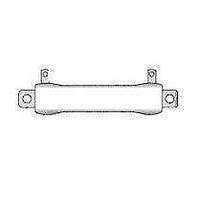
When limited space is a con-
sideration, choose Ohmite’s
“thin” stackable 250 Type
resistors. These oval-shaped
ceramic-core resistors feature
a low profile to permit instal-
lation in spaces with height
restrictions. They are also
equipped with integral mount-
ing brackets so they can be
fastened to a chassis and
stacked in locations with lim-
ited surface area.
the mounting brackets add
a heat sinking benefit result-
ing in a smaller size per watt.
Durable 250 Type resistors are
fully welded and coated with
lead free vitreous enamel.
F E A T u r E S
• Small size-to-power ratio.
• Stackable
• Integral mounting bracket con-
• Low profile for use in equipment
Ohmite Mfg. Co.
10
15
20
25
30
40
Coating
Blank = Vitreous
ducts heat to mounting surface.
where space is limited.
See web-
core info
Series
Vitreous enamel:
25 = 250 Fixed
26 = 260 Adjustable
Silicone ceramic:
45 = 450 Fixed
46 = 460 Adjustable
1
1.5 –––1R5E
2
3
4
5
7.5 –––7R5E
custom
site for
When properly fastened,
C = Centohm
S = Silicone
Part No.
Prefix
Suffix
–––1R0E
–––2R0E
–––3R0E
–––4R0E
–––5R0E
–––10RE
–––15RE
–––20RE
–––25RE
–––30RE
–––40RE
� � � � � � � �
Series
o r d e r i n g i n f o
Wattage
See “Resistor Terminals for Tubular Cores”
� � � � � � � � � � � � � � �
Wattage &
Core Code
See “Core and
Terminal Selection”
1600 Golf Rd., Rolling Meadows, IL 60008 • 1-866-9-OHMITE • Int’l 1-847-258-0300 • Fax 1-847-574-7522 • www.ohmite.com • info@ohmite.com
Tolerance
F = 1%
H = 3%
J = 5%
K = 10%
Wattage
m a d e - t o - o r d e r p a r t S
RoHS Compliant
Ohms
1R0 = 1 Ω
250 = 250 Ω
1K0 = 1,000 Ω
25K = 25,000 Ω
25K5 = 25,500 Ω
Terminal Type
Mounting Brackets
(user supplies bracket for core TB)
B = Stacking box
S = Stacking stud, std. height
H = Stacking stud high
U = Unit type
1,000
1,250
• All-welded construction.
• RoHS compliant product avail-
S P E c i F i c A T i O N S
Material
Coating: Lead free vitreous
Core: Ceramic.
Terminals: Tinned lug with hole.
Derating: Linearly from 100% @
Electrical
Tolerance: ±5% (J)
Power rating: Based on mount-
Overload: 10x rated wattage for
Temperature coefficient:
100
150
200
250
300
400
500
750
800
50
75
able. Add “E” suffix to part num-
ber to specify.
enamel.
RoHS solder composition is 96%
Sn, 3.5% Ag, 0.5% Cu
+25°C to 0% @ +350°C.
ing a single resistor on a metal
surface measuring 10” (254mm)
square by 0.04” (1.016mm)
thick. Reduce rating by 15%
when mounting on non-metallic
surface.
5 seconds if max. voltage is not
exceeded.
–––50RE
–––75RE
–––100E
–––150E
–––200E
–––250E
–––300E
–––400E
–––500E
–––750E
–––800E
–––1K0E
–––1K25E
Part No.
Prefix
Suffix
S t a n d a r d p a r t n u m b e r S f o r 2 5 0 S e r i e S
1 to 20Ω: ±400 ppm/°C.
Over 20Ω: ±260 ppm/°C
Dielectric withstanding
voltage: 500 VAC: 10 and
20 watt rating. 1000 VAC:
30, 40 and 55 watt rat-
ing (measured from lug to
mounting bracket)
To calculate max. amps:
use the formula √P/R
Tolerance
J = 5%
Wattage
Ohms
Example:
1R00 = 1 Ω
250R = 250 Ω
1K00 = 1,000 Ω
25K0 = 25,000 Ω
25K5 = 25,500 Ω
RoHS
Compliant
10,000
15,000
20,000
25,000
40,000
Note:
and improve power dissipation.
1,500
2,000
2,500
3,000
4,000
5,000
6,000
7,500
*Reference dimension only; varies according to resistance value.
Series Wattage Ohms
4.979 mm
3.175 mm
Adjustable versions available. Consult Ohmite.
Other sizes available. Consult Ohmite.
Also available in low cost Centohm or Silicone coating. Consult Ohmite.
* Maximum Voltage is based on Ohm’s Law [V=√P*R] as limited by the resistance
value of specified product
6.350 mm
3.175 mm
2.776 mm
6.350 mm
F10
F20
F30
F40
F55
0.110":
0.196"
0.125"
3.175 mm
0.250"
0.125"
0.794 mm
Diam.
0.250"
Diam.
When resistors are stacked, use washers or spacers as required to insure clearance
–––1K5E
–––2K0E
–––2K5E
–––3K0E
–––4K0E
–––5K0E
–––6K0E
–––7K5E
–––10KE
–––15KE
–––20KE
–––25KE
–––40KE
Part No.
Prefix
Suffix
0.031"
0.125"
10
20
30
40
55
1.0-15K
1.0-50K
1.0-10K
1.0-25K
1.0-30K
Wattage
30W, 40W & 55W
10W & 20W
Diam.
0.063"
1.588 mm
Diam.
0.109"
2.776 mm
A
A
L
L
0.750 / 19.050
2.000 / 50.800
1.250 / 31.750
2.000 / 50.800
3.500 / 88.900
Length L
3.175 mm
4.763 mm
Dimensions (in. /mm)
0.125"
0.188"
Vitreous Enamel Power
= Standard values; check availability
250 Series
using the worldwide inventory
search at www.ohmite.com
0.375"
9.525 mm
0.438"
11.113 mm
1.000 / 25.400
2.313 / 58.750
2.000 / 50.800
2.750 / 69.850
4.250 / 107.950
‘Thin’ Stackohm
Length A
0.625"
15.875 mm
0.125" *
3.175 mm
0.250" *
6.350 mm
Voltage*
Max.
1405
187
815
281
655
33
®
Related parts for F20J10KE
Image
Part Number
Description
Manufacturer
Datasheet
Request
R

Part Number:
Description:
RESISTOR POWER 1.0 OHM 50W
Manufacturer:
Ohmite
Datasheet:

Part Number:
Description:
POINTER BAR KNOB, 6.35MM
Manufacturer:
Ohmite
Datasheet:

Part Number:
Description:
HAND WHEEL POINTER KNOB, 9.525MM
Manufacturer:
Ohmite
Datasheet:

Part Number:
Description:
FINGER GRIP KNOB, 3.175MM
Manufacturer:
Ohmite
Datasheet:


Part Number:
Description:
MOUNTING CLIP, 90 SERIES RESISTOR
Manufacturer:
Ohmite
Datasheet:

Part Number:
Description:
ADJUSTABLE LUG FOR DIVIDOHM
Manufacturer:
Ohmite
Datasheet:
Part Number:
Description:
ADJUSTABLE LUG FOR DIVIDOHM
Manufacturer:
Ohmite
Datasheet:


Part Number:
Description:
RESISTOR POWER 1.0 OHM 50W
Manufacturer:
Ohmite
Datasheet:
Part Number:
Description:
HAND WHEEL POINTER KNOB, 9.525MM
Manufacturer:
Ohmite
Datasheet:
Part Number:
Description:
RHEOSTAT REPAIR KIT
Manufacturer:
Ohmite
Datasheet: