1716030000 Weidmuller, 1716030000 Datasheet
1716030000
Specifications of 1716030000
281-1436
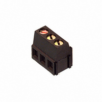
LM 5.08/90/3


Related parts for 1716030000


1716030000 Summary of contents
Page 1
Printed Circuit Board Terminals Weidmüller’s ever expanding range of printed circuit board terminals have been designed to cater for the many varied application requirements faced by todays Design Engineers. To solve these needs, we have produced a range of pcb ...
Page 2
The easy way to the right PCB Terminal Select the: 1. Rated cross-section ≤ 1 ≤ 2 ≤ 4 Pitch 3.50 mm 5.00 mm 5. Orientation (cable entry angle) ...
Page 3
Reliable connections Screw clamp - tension clamp We supply the best connection for every application. All connection systems, whether screw clamp or tension clamp are 100 % reliable, maintenance-free and easy to use. Practical accessories A well thought-out range of ...
Page 4
Product Selection Matrix Rated- cross-section Pitch in mm Construction Orientation Connection single-level 90° Leaf spring Screw clamp TOP connection Push-on tab Tension clamp 90° Screw clamp with test point 90° disconnection element w. test point 90° Screw clamp raised profile ...
Page 5
LP 5.08/90 LP 7.50/90 LP 7.62/ LPP 5.08/90 LPP 7.50/90 LPP 7.62/ Sp LPTR 5.08/ LP1N 5.08/ LP1H ...
Page 6
Product Features Quick and reliable product selection Wire cross-section Weidmüller supplies PCB terminals for rated cross-sections ≤ 1.5 mm ≤ 2 ≤ 4 ≤ 10.0 mm ≤ 25 Please see the ...
Page 7
Test points For some applications it can be important to know if the connection is live. For this purpose Weidmüller supplies various single-level PCB terminals with integrated test point. Leaf spring connection The leaf spring connection is the simplest screw ...
Page 8
Construction Single-level, low 90° Leaf spring connection Screwdriver Wire PCB The wire is introduced parallel to the PCB. The clamping screw is perpendicular to the PCB. Tension clamp connection Screwdriver Wire PCB The wire is introduced parallel to the PCB. ...
Page 9
Single-level, 180° Screw clamp connection Wire Screwdriver PCB The wire is introduced perpendicular to the PCB. The clamping screw is parallel to the PCB. TOP connection Screwdriver Wire PCB The wire is inserted perpendicular to the PCB, and parallel to ...
Page 10
Rated cross-section ≤ 1 5.08/90 Technical Data VDE UL Rated voltage V 250* 300 Rated current A 17 Clamping range max. mm /AWG 1.5 14 *Overvoltage category III / Pollution severity 3 Additional technical data see ...
Page 11
Rated cross-section ≤ 1 3.5/90 Technical Data VDE UL CSA Rated voltage V 125* 300 300 Rated current Clamping range max. mm /AWG 1 *Overvoltage category III / Pollution severity 3 ...
Page 12
Rated cross-section ≤ 1.5 mm LM2N 3.5/90 Technische Daten Technical Data VDE VDE UL UL Rated voltage V 125* 300 Rated current Clamping range max. mm /AWG 1.5 14 *Overvoltage category III / Pollution severity 3 ...
Page 13
Rated cross-section ≤ 1 5.00/90 Technical Data VDE UL CSA Rated voltage V 250* 300 300 Rated current A 17 Clamping range max. mm /AWG 1 *Overvoltage category III / Pollution severity 3 ...
Page 14
... III / Pollution severity 3 Additional technical data see page 53 Solder pin length 3.5 mm 3.5 mm Colour Poles Type Cat. No. Cat. No 5.08/2/90 1716080000 1716020000 500 3 LM 5.08/3/90 1716090000 1716030000 500 Accessories Marking Fixing Miscellaneous 16 2 LM1N 5.08/90 CSA CSA Technical Data VDE 300 Rated voltage V ...
Page 15
Rated cross-section ≤ 1 5.08/135 Technical Data VDE UL CSA Rated voltage V 250* 300 300 Rated current A 17 Clamping range max. mm /AWG 1 *Overvoltage category III / Pollution severity 3 ...
Page 16
Rated cross-section ≤ 1.5 mm LM2H 5.08/90 Technical Data VDE UL Rated voltage V 250* 300 Rated current Clamping range max. mm /AWG 1.5 14 *Overvoltage category III / Pollution severity 3 Additional technical data see ...
Page 17
Rated cross-section ≤ 1.5 mm LMZF 5.08/90 Technical Data VDE UL CSA Rated voltage V 250* 300 300 Rated current Clamping range max. mm /AWG 1 *Overvoltage category III / Pollution severity 3 ...
Page 18
Rated cross-section ≤ 1.5 mm LM2NZF 5.08/135 Technische Daten Technical Data VDE VDE UL UL Rated voltage V 250* 300 Rated current Clamping range max. mm /AWG 2.5 12 *Overvoltage category III / Pollution severity 3 ...
Page 19
Rated cross-section ≤ 1.5 mm TOP 1.5GS 5.08/90 block construc- tion Technische Daten Technical Data VDE VDE UL UL CSA CSA Rated voltage V 250* 300 300 Rated current Clamping range max. mm /AWG 1.5 ...
Page 20
Rated cross-section ≤ 1.5 mm TOP 1.5GS 7.62/90 modular construc- tion Technical Data VDE UL Rated voltage V 500* 300 Rated current Clamping range max. mm /AWG 1.5 14 *Overvoltage category III / Pollution severity 3 ...
Page 21
Rated cross-section ≤ 2 5.00/90 Technical Data VDE UL CSA Rated voltage V 250* 300 300 Rated current Clamping range max. mm /AWG 4 *Overvoltage category III / Pollution severity 3 ...
Page 22
Rated cross-section ≤ 2 5.00/135 with test point Technical Data VDE UL Rated voltage V 250* 300 Rated current Clamping range max. mm /AWG 4.0 12 *Overvoltage category III / Pollution severity 3 Additional ...
Page 23
Rated cross-section ≤ 2 5.08/90 Technical Data VDE UL CSA Rated voltage V 250* 300 300 Rated current Clamping range max. mm /AWG 4 *Overvoltage category III / Pollution severity 3 ...
Page 24
Rated cross-section ≤ 2.5 mm LP1H 5.08/90 Technical Data VDE UL Rated voltage V 250* 300 Rated current Clamping range max. mm /AWG 4.0 12 *Overvoltage category III / Pollution severity 3 Additional technical data see ...
Page 25
Rated cross-section ≤ 2.5 mm LP2N 5.08/90 Technical Data VDE UL CSA Rated voltage V 250* 300 300 Rated current Clamping range max. mm /AWG 4 *Overvoltage category III / Pollution severity 3 ...
Page 26
Rated cross-section ≤ 2.5 mm LP3R 5.08/90 Technical Data VDE UL Rated voltage V 250* 300 Rated current Clamping range max. mm /AWG 4.0 12 *Overvoltage category III / Pollution severity 3 Additional technical data see ...
Page 27
Rated cross-section ≤ 2 7.50/90 Technical Data VDE UL CSA Rated voltage V 500* 300 300 Rated current Clamping range max. mm /AWG 4 *Overvoltage category III / Pollution severity 3 ...
Page 28
Rated cross-section ≤ 2 7.50/180 Technical Data VDE UL Rated voltage V 500* 300 Rated current Clamping range max. mm /AWG 4.0 12 *Overvoltage category III / Pollution severity 3 Additional technical data see ...
Page 29
Rated cross-section ≤ 2.5 mm LPP 7.62/90 with test point Technical Data VDE UL CSA Rated voltage V 500* 300 300 Rated current Clamping range max. mm /AWG 4 *Overvoltage category III / ...
Page 30
Rated cross-section ≤ 2 10.00/90 Technical Data VDE UL Rated voltage V 630* 300 Rated current Clamping range max. mm /AWG 4.0 12 *Overvoltage category III / Pollution severity 3 Additional technical data see ...
Page 31
Rated cross-section ≤ 4 9.5/90 Technische Daten VDE UL CSA Rated voltage V 630* 300 300 Rated current Clamping range max. mm /AWG 4 *Overvoltage category III / Pollution severity 3 ...
Page 32
Rated cross-section ≤ 4.0 mm TOP4GS 7.62/90 Technical Data VDE UL Rated voltage V 500* 300 Rated current Clamping range max. mm /AWG 6.0 10 *Overvoltage category III / Pollution severity 3 Additional technical data see ...
Page 33
Rated cross-section ≤ 10.0 mm GSE 10/180 with test point Technical Data VDE UL CSA Rated voltage V 400* 300 300 Rated current Clamping range max. mm /AWG 10.0 8 *Overvoltage category III / Pollution ...
Page 34
Rated cross-section ≤ 25 15.00/90 with test point Technical Data VDE UL Rated voltage V 800* 600 Rated current A 101 85 2 Clamping range max. mm /AWG 25.0 4 *Overvoltage category III / Pollution severity 3 Additional ...
Page 35
Push-on Tab Connection GSF 5/90 Technical Data VDE UL CSA Rated voltage V* 200 300 300 Rated current Clamping range max. mm /AWG 2.5 - *Overvoltage category III / Pollution severity 3 Additional technical data ...
Page 36
Accessories 38 The Weidmueller portfolio of printed circuit board terminals is complemented by a wide range of accessories to cover virtually every installation requirement. These accessories comprise mountings for LED’s to monitor the switching state, numerous marking systems, fuse inserts, ...
Page 37
Accessories Selection Matrix Marking systems Rated PCB Terminal Page cross- 40-42 section Accessories PM 5.08 KSW 4, KSW 2 KSW 2.5 MK 7.5 KSW 2.5 1 3.5 all versions KSW 4, KSW 2.5 LM 5.00 ...
Page 38
The Dekafix marking system can be used with the LX 15.00, LU 10.16 and GSE 10 as well as with the System LP (with the exception of LPZF and its accessories). Dekafix is supplied in packs of 10 cards with ...
Page 39
System WS 3 The white WS 3 marker tags are used to mark LPA TR disconnect elements. Each pack marker tags contains 20 stars with 10 tags each. Ordering data Print Cat. No. individual letters A 1055761021 ...
Page 40
Marking Strips KSW The white self-adhesive KSW marking strips are available in 2 widths: KSW 4 Width (mm) Pitch also suitable for 4.0 3.50 mm – 5.08 mm 5.00 mm 7.50 mm 7.62 mm 10.16 mm KSW 4 can be ...
Page 41
LED Holder LPA FA The LED holders and the marker carriers are latched onto the rear of the PCB terminals. 3 versions are available: The LP FA LED holder permits an LED to be mounted reliably and easily visible onto ...
Page 42
Fuse Holder In combination with X (mm) LP 5.08/ …/90 12.84 LPP 5.08/…/90 15.24 The LPA SI fuse holder will accept G-fuses (DIN 820 or IEC127/part 2). The power loss is 1.6 W. ...
Page 43
Screwdriver SDI SD Ordering data Type Clamping screw Product Cat. No. SDI M2 LM3.5 9008370000 0 M2.5 LM 5.0x 9008330000 0.6 x 3.5 x 100 TOP1.5GS LMT 5. 7.5 SD ...
Page 44
Adaptor Plates LPZP/90 Thickness 2.54 mm (a) Type Cat. No. LPZP 2.54/90 OR 1747480000 Thickness 1.27 mm (a) Type Cat. No. LPZP 1.27/90 OR 1747490000 Please see processing notes and application examples on page 47-48. Fixing Plates LPHP Type Cat. ...
Page 45
Application Examples of System LP - Adaptor Plates LPZP 2.54/90 Fig. 1 Fig. 2 Fig. 3 LPZP 2.54/90 adaptor plate to create optical separation and pitch stepping (s. fig. 1-3, 9-16) with printed circuit board versions of 90° and 180° ...
Page 46
Application Examples of System LP - Adaptor Plates Mixed pitches Fig. 10 Fig. 11 Fig. 12 Fig. 13 Fig. 14 Fig. 15 Fig. 16 The single-pole LP permits mixed pitches to be combined easily if this is not possible using ...
Page 47
49 ...
Page 48
Technical Data / Derating Curves Materials Insulation material 1) Colour Temperature range Flammability class. Contact base material Contact plating System characteristic values Pitch Connection method Solder pin length PCB hole diameter Insulation stripping length Clamping screw Insulation resistance Through resistance ...
Page 49
Technical Data / Derating Curves Materials Insulation material 1) Colour Temperature range Flammability class. UL94 Contact base material Contact plating System characteristic values Pitch mm Connection method Solder pin length mm PCB hole diameter Ømm Insulation stripping length mm Clamping ...
Page 50
Technical Data / Derating Curves Materials Insulation material 1) Colour Temperature range Flammability class. Contact base material Contact plating System characteristic values Pitch Connection method Solder pin length PCB hole diameter Insulation stripping length Clamping screw Insulation resistance Through resistance ...
Page 51
Technical Data / Derating Curves Materials Insulation material 1) Colour Temperature range Flammability class. UL94 Contact base material Contact plating System characteristic values Pitch mm Connection method Solder pin length mm PCB hole diamter Ømm Insulation stripping length mm Clamping ...
Page 52
Technical Data / Derating Curves Materials Insulation material 1) Colour Temperature range Flammability class. Contact base material Contact plating System characteristic values Pitch Connection method Solder pin length PCB hole diamter Insulation stripping length Clamping screw Insulation resistance Through resistance ...
Page 53
Technical Data / Derating Curves Materials Insulation material 1) Colour Temperature range Flammability class. UL94 Contact base material Contact plating System characteristic values Pitch mm Connection method Solder pin length mm PCB hole diamter Ømm Insulation stripping length mm Clamping ...
Page 54
Technical Data / Deratingkurven Materials Insulation material 1) Colour Temperature range Flammability class. Contact base material Contact plating System characteristic values Pitch Connection method Solder pin length PCB hole diamter Insulation stripping length Clamping screw Insulation resistance Through resistance Torque ...
Page 55
Technical Data / Derating Curves Materials Insulation material 1) Colour Temperature range Flammability class. UL94 Contact base material Contact plating System characteristic values Pitch mm Connection method Solder pin length mm PCB hole diamter Ømm Insulation stripping length mm Clamping ...
Page 56
Technical Data / Derating Curves Materials Insulation material 1) Colour Temperature range Flammability class. Contact base material Contact plating System characteristic values Pitch Connection method Solder pin length PCB hole diamter Insulation stripping length Clamping screw Insulation resistance Through resistance ...
Page 57
Technical Data / Derating Curves Materials Insulation material 1) Colour Temperature range Flammability class. UL94 Contact base material Contact plating System characteristic values Pitch mm Connection method Solder pin length mm PCB hole diamter Ømm Insulation stripping length mm Clamping ...
Page 58
Technical Data / Derating Curves Materials Insulation material 1) Colour Temperature range Flammability class. Contact base material Contact plating System characteristic values Pitch Connection method Solder pin length PCB hole diamter Insulation stripping length Clamping screw Insulation resistance Through resistance ...
Page 59
Technical Data / Derating Curves Materials Insulation material 1) Colour Temperature range Flammability class. UL94 Contact base material Contact plating System characteristic values Pitch mm Connection method Solder pin length mm PCB hole diamter Ømm Insulation stripping length mm Clamping ...
Page 60
Technical Data / Derating Curves Materials Insulation material 1) Colour Temperature range Flammability class. Contact base material Contact plating System characteristic values Pitch Connection method Solder pin length PCB hole diamter Insulation stripping length Clamping screw Insulation resistance Through resistance ...
Page 61
Technical Data / Derating Curves Materials Insulation material 1) Colour Temperature range Flammability class. UL94 Contact base material Contact plating System characteristic values Pitch mm Connection method Solder pin length mm PCB hole diamter Ømm Insulation stripping length mm Clamping ...
Page 62
Technical Data / Derating Curves Materials Insulation material 1) Colour Temperature range Flammability class. Contact base material Contact plating System characteristic values Pitch Connection method Solder pin length PCB hole diamter Insulation stripping length Clamping screw Insulation resistance Through resistance ...
Page 63
Technical Data / Derating Curves Materials Insulation material 1) Colour Temperature range Flammability class. Glow-wire test Contact base material Contact plating System characteristic values Pitch Connection method Solder pin length PCB hole diamter Insulation stripping length Clamping screw Insulation resistance ...
Page 64
66 ...