Standard Resistance Range ........................................................................................................................................................................................... 5 K - 100 K ohms
Total Resistance Tolerance ...............................................................................................................................................................................................................±20 %
Independent Linearity .........................................................................................................................................................................................................................±5 %
End Resistance...............................................................................................................................................................................................................2 ohms maximum
Effective Electrical Angle
Contact Resistance Variation .............................................................................................................................................................................................. 3 % maximum
Dielectric Withstanding Voltage (MIL-STD-202, Method 301)
Insulation Resistance ...........................................................................................................................................................................................100 megohms minimum
Power Rating @ 70 ºC (Derated to 0 @ 125 °C)
Rotary Switch Type.................................................................................................................................................................................................................... SPST N.O.
Momentary Push Switch Type ................................................................................................................................................................................................... SPST N.O.
Operating Temperature Range .......................................................................................................................................................... -40 °C to +85 °C (-40 °F to +185 °F)
Storage Temperature Range ............................................................................................................................................................. -55 °C to +85 °C (-67 °F to +185 °F)
Vibration ..............................................................................................................................................................................................................................................15 G
Shock ..................................................................................................................................................................................................................................................30 G
Load Life .................................................................................................................................................................................................................................. 1,000 Hours
Rotational Life (No Load) ...................................................................................................................................................................................................... 50,000 cycles
Switch Life
Moisture Resistance ................................................................................................................................................................... MIL-STD-202, Method 103, Condition B
IP Rating ............................................................................................................................................................................................................................................. IP 40
Stop Strength ...........................................................................................................................................................................................................19.8 N-cm (28 oz.-in.)
Mechanical Angle
Torque
Shaft Retentiion
Weight (Single Section)...................................................................................................................................................................................................4 grams (0.14 oz.)
Terminals
Marking ................................................................................................................................................................ Manufacturer’s trademark, part number and date code
Ganging .............................................................................................................................................................................................................................1 cup maximum
Hardware .............................................................One lockwasher and one mounting nut is shipped with each potentiometer, except where noted in the part number
Packaging .............................................................................................................................................................................................................................. 100 pcs./tray
Electrical Characteristics
Switch Characteristics
Environmental Characteristics
Mechanical Characteristics
Non-Switch Type (Bushing Type “S”) ..................................................................................................................................................................................220 ° ± 5 °
Rotary Switch Type (Bushing Type “S”) ................................................................................................................................................................................220 ° ±5 °
Momentary Push Switch Type (Bushing Type “L”) ............................................................................................................................................................ 201 ° ±5 %
Sea Level .............................................................................................................................................................................................................750 VRMS minimum
(Voltage Limited by Power Dissipation or 350 VAC, whichever is less)
Linear Taper ...........................................................................................................................................................................................................................0.25 watt
Audio Taper ..........................................................................................................................................................................................................................0.125 watt
Power Rating (Resistive Load) ............................................................................................................................................................................. 1.5 amps @ 12 VDC
Contact Resistance @ 10 mA ........................................................................................................................................................................200 milliohms maximum
Contact Bounce .............................................................................................................................................................................................................5 milliseconds
Actuation Torque .................................................................................................................................................................................. 0.7 to 4.9 N-cm (1 to 7 oz.-in.)
Power Rating (Resistive Load) ...................................................................................................................................................................... 250 milliamps @ 12 VDC
Contact Resistance @ 10 mA (w/500 gm Shaft Load) ...........................................................................................................................................50 ohms maximum
Contact Bounce .............................................................................................................................................................................................................5 milliseconds
Actuation Force .......................................................................................................................................................................................................... 500 ± 100 gram
Total Resistance Shift ..................................................................................................................................................................................................................±3 %
Voltage Ratio Shift .......................................................................................................................................................................................................................±5 %
Total Resistance Shift ................................................................................................................................................................................................................±10 %
Total Resistance Shift ................................................................................................................................................................................................................±10 %
Rotary Switch Type ........................................................................................................................................................................................................ 25,000 cycles
Momentary Push Switch Type ....................................................................................................................................................................................... 50,000 cycles
Total Resistance Shift ................................................................................................................................................................................................................±10 %
Non-Switch and Rotary Switch Type ..................................................................................................................................................................................270 ° ±10 °
Momentary Push Switch Type ............................................................................................................................................................................................230 ° ±10 °
Starting .......................................................................................................................................................................0.07 to 0.70 N-cm (0.1 to 1.0 oz.-in.) minimum
Running....................................................................................................................................................................0.07 to 0.53 N-cm (0.1 to 0.75 oz.-in.) maximum
Mounting ...........................................................................................................................................................................1.7 to 2.0 N-m (15 to 18 lbs.-in.) maximum
Pull Force .........................................................................................................................................................................................................4 Kg (8.8 lb.) maximum
Push Force .....................................................................................................................................................................................................4.5 Kg (10 lb.) maximum
Potentiometer ...................................................................................................................................................................................... Printed circuit board terminals
Switch ............................................................................................................................................................................................................................. Flat terminals
Soldering Condition
Manual Soldering ..................................................................96.5Sn/3.0Ag/0.5Cu solid wire or no-clean rosin cored wire; 370 °C (700 °F) max. for 3 seconds
Wave Soldering .......................................................................................... 96.5Sn/3.0Ag/0.5Cu solder with no-clean fl ux; 260 °C (500 °F) max. for 5 seconds
Wash processes ............................................................................................................................................................................................. Not recommended
Features
■
■
■
■
■
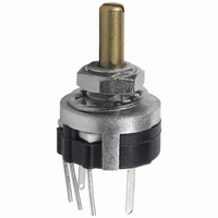
39 – 13 mm Single Turn Panel Control with Switch Option
Conductive plastic technology
Low profi le package
50,000 cycle rotational life
Available with momentary push or rotary
switch option
PCB mount terminal confi guration
Customers should verify actual device performance in their specifi c applications.
*RoHS Directive 2002/95/EC Jan 27, 2003 including Annex.
■
■
■
Rugged metal housing for industrial
applications
Flatted or slotted shaft options
RoHS compliant*
Specifi cations are subject to change without notice.