4609M-901-102LF Bourns Inc., 4609M-901-102LF Datasheet
4609M-901-102LF
Manufacturer Part Number
4609M-901-102LF
Description
RESISTORS NETWORK - CAPACITOR
Manufacturer
Bourns Inc.
Type
Ceramicr
Datasheet
1.4609M-901-102LF.pdf
(1 pages)
Specifications of 4609M-901-102LF
Capacitance
1000pF
No. Of Capacitors
8
Tolerance (+ Or -)
20%
Voltage
50VDC
Number Of Terminals
9Terminal
Temp Coeff (dielectric)
X7R
Operating Temp Range
-55C to 125C
Mounting Style
Through Hole
Package / Case
SIP
Construction
Single-In-Line
Failure Rate
Not Required
Product Height (mm)
6.35mm
Product Depth (mm)
3.81mm
Product Length (mm)
22.81mm
Lead Diameter (nom)
0.508mm
Terminal Pitch
2.54mm
Lead Free Status / Rohs Status
Compliant
Capacitance Tolerance
Circuit Confi guration ... Isolated, bussed
Capacitor Dielectric ................NPO, X7R
Capacitance Voltage Rating
Lead Spacing ............ 0.100 ” (2.54 mm)
Terminal Coating ..........Sn/Ag/Cu-plated
Body Material ............. Epoxy/Anhydride
4610M-901-103LF
4610M-902-103LF
4610M-901-104LF
4610M-902-104LF
Model
Number of Pins
Profi le
Electrical Confi guration
Capacitance Code
Terminations
Consult factory for other available options.
Electrical Characteristics
Physical Characteristics
Standard High Volume Part Numbers
How To Order
39 pF - 270 pF ......................... ±10 %
>270 pF - 0.1 μF ...................... ±20 %
39 pF - 270 pF ..NPO - 50 V @ +25 °C
>270 pF - 0.047 μF
(46 = SIP Pkg)
(M = Standard Profi le)
• 901 = Bussed
• 902 = Isolated
• 904 = Dual-Bussed
• First 2 digits are signifi cant
• Third digit represents the
• LF = Lead free (Sn/Ag/Cu-plated)
...........................X7R - 50 V @ +25 °C
number of zeros to follow.
46 10 M - 901 - 103 LF
conformal material
and dual-bussed
Features
■
■
■
■
Represents total content. Layout may
vary.
These are the standard and non-standard capacitance values available. Consult
factory for capacitance values and types outside this range. Tolerances of 5 %, 10 %
and 20 % are available.
900 Series - Capacitor Networks
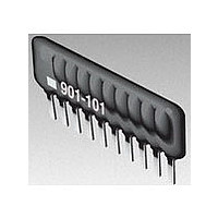
Typical Part Marking
Capacitance
Product Dimensions
Standard Capacitance Values and Codes
Integrates capacitor function in one
package
RoHS compliant*
Design reduces termination noise
Popular standard capacitance values
available
“NPO” DIELECTRICS
(pF)
100
120
150
180
220
270
39
47
56
68
82
(.020 ± .002)
PIN ONE
INDICATOR
10 % Tolerance
.508 ± .050
(.100 ± .003*)
NON-ACCUM.
(.010 ± .039)
2.54 ± .07
.254 ± .10
(.150)
3.81
MODEL
PIN #1
TYP.
REF.
MAX.
TYP.
Capacitance
901-101
TYP.
MAXIMUM
Code
390
470
560
680
820
101
121
151
181
221
271
A
CAPACITANCE
CODE?
Count
Pin
10
11
12
13
14
4
5
6
7
8
9
(.138 ± .020)
(.200)
Customers should verify actual device performance in their specifi c applications.
MAX.
5.08
3.50 ± .50
mm (Inches)
Capacitance
A Maximum
28.0 (1.102)
30.5 (1.201)
33.1 (1.303)
35.6 (1.402)
“X7R” DIELECTRICS
10.2 (.402)
12.7 (.500)
15.3 (.602)
17.8 (.701)
20.4 (.803)
22.9 (.902)
25.4 (1.00)
1000
1200
1500
1800
2200
2700
3300
3900
4700
5600
6800
8200
(pF)
330
390
470
560
680
820
20 % Tolerance
*RoHS Directive 2002/95/EC Jan 27, 2003 including Annex.
Capacitance
■
■
These models incorporate 2 to 12
capacitors of equal value, each
connected to a dual buss that connects
Pin 1 to the last pin.
These models incorporate 2 to 7
isolated capacitors of equal value, each
connected between two pins.
These models incorporate 3 to 13
capacitors of equal value, each
connected between a common bus
(Pin 1) and a separate pin.
Isolated, bussed and dual-bussed circuits
available
Compatible with wave soldering
1
1
Code
Dual-Bussed Capacitors (904 Circuit)
Isolated Capacitors (902 Circuit)
Bussed Capacitors (901 Circuit)
1
331
391
471
561
681
821
102
122
152
182
222
272
332
392
472
562
682
822
Specifi cations are subject to change without notice.
4
Capacitance
“X7R” DIELECTRICS
0.012
0.015
0.018
0.022
0.027
0.033
0.039
0.047
0.056
0.068
0.082
0.01
6
(μF)
0.1
...
20 % Tolerance
10
Capacitance
REV. 11/10
12
Code
103
123
153
183
223
273
333
393
473
563
683
823
104
n-1
14
14
n
Related parts for 4609M-901-102LF
Image
Part Number
Description
Manufacturer
Datasheet
Request
R

Part Number:
Description:
RESISTORS NETWORK - THICK FILM CONFORMAL SIP W/SP PIN L
Manufacturer:
Bourns Inc.
Datasheet:

Part Number:
Description:
RESISTOR, BUS RES N/W, 8, 10KOHM, 2%, SIP
Manufacturer:
Bourns Inc.
Datasheet:
Part Number:
Description:
RESISTORS NETWORK - THICK FILM CONFORMAL SIP W/SP PIN L
Manufacturer:
Bourns Inc.
Part Number:
Description:
Manufacturer:
Bourns Inc.
Datasheet:
Part Number:
Description:
RESISTOR, BUS RES N/W, 8, 10KOHM, 2%, SIP
Manufacturer:
Bourns Inc.
Datasheet:

Part Number:
Description:
Resistor Networks & Arrays 9pins 2.2Kohms Bussed
Manufacturer:
Bourns Inc.
Datasheet:

Part Number:
Description:
Manufacturer:
Bourns, Inc.
Datasheet:
Part Number:
Description:
11mm Potentiometer
Manufacturer:
Bourns, Inc.
Datasheet: