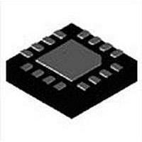
MAX17149ETE+ Maxim Integrated Products, MAX17149ETE+ Datasheet

MAX17149ETE+
Specifications of MAX17149ETE+
Related parts for MAX17149ETE+
MAX17149ETE+ Summary of contents
Page 1
... S Output Overvoltage Protection S Small 16-Pin, 3mm x 3mm Thin QFN Package Notebook, Subnotebook, and Tablet Computer Displays Automotive Systems Handy Terminals PART MAX17129ETE + MAX17149ETE+ +Denotes lead(Pb)-free/RoHS-compatible package. *EP = Exposed pad. Simplified Operating Circuit appears at end of data sheet. Features Applications Ordering Information TEMP RANGE ...
Page 2
Low-Cost, 6-String WLED Drivers with Quick-PWM Step-Up Converter ABSOLUTE MAXIMUM RATINGS FSEL, IN, BRT GND ..................................-0.3V to +28V FB_, LX, OVP to PGND .........................................-0.3V to +48V PGND to GND ......................................................-0.3V to +0. GND .............................................................-0.3V to +6V ...
Page 3
Low-Cost, 6-String WLED Drivers with ELECTRICAL CHARACTERISTICS (continued) (Circuit of Figure 12V 100kI ISET PARAMETER 0.3V < V FSEL Bias Current 4.1V < V LED CURRENT SOURCE ISET Resistance Range R ISET R ...
Page 4
Low-Cost, 6-String WLED Drivers with Quick-PWM Step-Up Converter ELECTRICAL CHARACTERISTICS (Circuit of Figure 12V 100kI ISET PARAMETER IN not connected Input Voltage Range Quiescent ...
Page 5
Low-Cost, 6-String WLED Drivers with ELECTRICAL CHARACTERISTICS (continued) (Circuit of Figure 12V 100kI ISET PARAMETER FB_ On-Resistance V FB_ V FB_ FB_ Leakage Current V FB_ FB_ On-Time BRT Input High Level BRT ...
Page 6
Low-Cost, 6-String WLED Drivers with Quick-PWM Step-Up Converter (Circuit of Figure 12V +25°C, unless otherwise noted LED CURRENT (I LED 100% BRIGHTNESS) vs. INPUT VOLTAGE 20.20 20.15 20.10 20.05 20. ...
Page 7
Low-Cost, 6-String WLED Drivers with (Circuit of Figure 12V +25°C, unless otherwise noted LED OPEN FAULT PROTECTION (BRIGHTNESS = 100%, LED OPEN ON FB1) 20mA 2ms/div LINE TRANSIENT RESPONSE = 9V ↔ 21V, ...
Page 8
Low-Cost, 6-String WLED Drivers with Quick-PWM Step-Up Converter PIN NAME PWM Signal Input. This PWM signal controls the LED brightness by turning the LED current sources on 1 BRT or off. Internal LDO Output. V Connect a minimum 1FF capacitor ...
Page 9
Low-Cost, 6-String WLED Drivers with PIN NAME Current-Balancer Output. LED string cathode connection. FB3 is the open-drain output of an internal 10 FB3 regulator, which controls current through FB3. FB3 can sink up to 45mA. If unused, connect FB3 to ...
Page 10
Low-Cost, 6-String WLED Drivers with Quick-PWM Step-Up Converter 26V C IN 4.7µF IN 0.1µ 1µF ISET R ISET 100kI EN BRT 100Hz TO 25kHz GND Figure 1. MAX17129 Typical Operating Circuit Table 1. Component ...
Page 11
Low-Cost, 6-String WLED Drivers with EN STARTUP IN 3.8V LDO V CC LOGIC-CIRCUIT SUPPLY CALCULATION FSEL FAULT CONTROL THERMAL SHUTDOWN ISET ISET EN BRT TEST AND OTP SMBus Figure 2. Functional Diagram Quick-PWM Step-Up Converter OFF-TIME ONE-SHOT ...
Page 12
Low-Cost, 6-String WLED Drivers with Quick-PWM Step-Up Converter Detailed Description The MAX17129/MAX17149 are high-efficiency drivers for arrays of white LEDs. They contain a Quick-PWM step-up controller, a 3.8V linear regulator, PWM dimming control circuit, internal power MOSFET, and six regulated ...
Page 13
Low-Cost, 6-String WLED Drivers with The actual switching frequency can be approximated by: − × × − I OFF OVP D where the forward voltage of ...
Page 14
Low-Cost, 6-String WLED Drivers with Quick-PWM Step-Up Converter Figure 5 shows possible supply connection configura- tions for the devices. The V pin should be bypassed CC to GND with a minimum 1FF ceramic capacitor. At startup, the devices perform an ...
Page 15
Low-Cost, 6-String WLED Drivers with Current-Source Fault Protection An LED fault open/short is detected after the startup. When one or more strings fail after the startup, the corre- sponding current source is disabled. The remaining LED strings still operate normally. ...
Page 16
Low-Cost, 6-String WLED Drivers with Quick-PWM Step-Up Converter inductor resistance is relatively high, more ripples can be accepted to reduce the number of required turns and increase the wire diameter. If the inductor resistance is relatively low, increasing inductance to ...
Page 17
Low-Cost, 6-String WLED Drivers with Output Capacitor Selection The total output-voltage ripple has two components: the capacitive ripple caused by the charging and discharging on the output capacitor, and the ohmic ripple due to the capacitor’s equivalent series resistance (ESR): ...
Page 18
Low-Cost, 6-String WLED Drivers with Quick-PWM Step-Up Converter PCB Layout Guidelines Careful PCB layout is important for proper operation. Use the following guidelines for good PCB layout: 1) Minimize the area of high current-switching loop of the rectifier diode, internal ...
Page 19
Low-Cost, 6-String WLED Drivers with Chip Information PROCESS: BiCMOS Quick-PWM Step-Up Converter FSEL PGND CC MAX17129 ISET OVP FB1 FB2 FB3 EN FB4 BRT FB5 GND FB6 EP For the latest package outline information and land pat ...
Page 20
... Maxim cannot assume responsibility for use of any circuitry other than circuitry entirely embodied in a Maxim product. No circuit patent licenses are implied. Maxim reserves the right to change the circuitry and specifications without notice at any time. Maxim Integrated Products, 120 San Gabriel Drive, Sunnyvale, CA 94086 408-737-7600 20 2010 Maxim Integrated Products © ...


