CRA04S0831K00JTD Vishay, CRA04S0831K00JTD Datasheet - Page 3
CRA04S0831K00JTD
Manufacturer Part Number
CRA04S0831K00JTD
Description
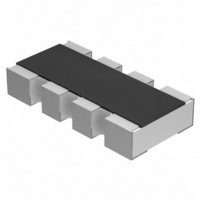
Resistor Network,Thick Film,1KOhms,50WV,5+/-% Tol,-200,200ppm-TC,0804-Case
Manufacturer
Vishay
Series
CRA04r
Type
Arrayr
Specifications of CRA04S0831K00JTD
Resistance (ohms)
1K
Number Of Resistors
4
Circuit Type
Isolated
Temperature Coefficient
±200ppm/°C
Tolerance
±5%
Power Per Element
62.5mW
Number Of Pins
8
Package / Case
0804 (2010 Metric), Convex
Size / Dimension
0.079" L x 0.039" W (2.00mm x 1.00mm)
Height
0.018" (0.45mm)
Mounting Type
Surface Mount
Operating Temperature
-55°C ~ 155°C
Technology
Thick Film
Resistance
1kohm
Power Rating Per Resistor
1/16W
Tolerance (+ Or -)
5%
Circuit Designator
ISOL
Mounting Style
Surface Mount
Military Standard
Not Required
Operating Temp Range
-55C to 155C
No. Of Terminals
8
Case Style
Molded
Failure Rate
Not Required
Termination Style
Convex
Terminal Pitch
0.5
Product Length (mm)
2mm
Product Depth (mm)
1mm
Product Height (mm)
0.45mm
Product Type
Arrays
Power Rating
0.126 Watt
Operating Temperature Range
- 55 C to + 155 C
Dimensions
1 mm W x 1 mm L x 0.35 mm H
Voltage Rating
50 Volts
Lead Free Status / RoHS Status
Lead free / RoHS Compliant
Lead Free Status / RoHS Status
Lead free / RoHS Compliant, Lead free by exemption / RoHS Compliant
Other names
CRA4S81.0KTR


CRA04S
Vishay
Notes
(1)
(2)
www.vishay.com
250
TEST PROCEDURES AND REQUIREMENTS
TEST
(clause)
Resistance (4.5)
Temperature coefficient (4.8.4.2)
Overload (4.13)
Solderability (4.17.5)
Resistance to soldering heat (4.18.2)
Rapid change of temperature (4.19)
Damp heat, steady state (4.24)
Climatic sequence (4.23)
Endurance at 70 °C (4.25.1)
Extended endurance (4.25.1.8)
Endurance at upper category
temperature (4.25.3)
APPLICABLE SPECIFICATIONS
• EN 60115-1
• EN 140400
• EN 140401-802
• IEC 60068-2-X
• EIA 481
Figures are given for a single element
Solderability is specified for 2 years after production or requalification. Permitted storage time is 20 years
(2)
Generic Specification
Sectional Specification
Detail Specification
Variety of environmental test procedures
Packaging of SMD components
For technical questions, contact: filmresistors.thickfilmchip@vishay.com
CONDITIONS OF TEST
Stability for product types:
16 h at UCT = 125 °C; 1 cycle at 55 °C;
U = U
U = U
30 min at UCT = 125 °C; 5 cycles
solder bath method; 235 °C; 2 s
Thick Film Resistor Array
Aging 4 h at 155 °C, dryheat
Duration extended to 8000 h
1 h/1 kPa at 15 °C to 35 °C;
30 min at LCT = - 55 °C;
(260 ± 5) °C; (10 ± 1) s
max.
max.
UCT = 125 °C; 1000 h
U = 2.5 × (P
1.5 h ON; 0.5 h OFF;
(40 ± 2) °C; 56 days;
2 h at LCT = - 55 °C;
Solder bath method;
visual examination
20/- 55/20 °C and
≤ 2 x U
5 cycles at 55 °C
; whichever is less severe
; whichever is less severe
U = (P
U = (P
(93 ± 3) % RH
70 °C; 1000 h
20/125/20 °C
max.
70
70
-
EN 60115-1
x R)
x R)
70
; 0.5 s
x R)
1/2
1/2
1/2
CRA04S
CLASS 1 OR BETTER
± (0.25 % R + 0.05 Ω)
± (0.25 % R + 0.05 Ω)
± (0.25 % R + 0.05 Ω)
± (1 % R + 0.05 Ω)
± (1 % R + 0.05 Ω)
± (1 % R + 0.05 Ω)
± (1 % R + 0.05 Ω)
± (2 % R + 0.1 Ω)
10 Ω to 1 MΩ
± 100 ppm/K
STABILITY
PERMISSIBLE CHANGE (ΔR/R)
± 1 %
Good tinning (≥ 95 % covered)
REQUIREMENTS
no visible damage
Document Number: 31043
CLASS 2 OR BETTER
± (0.5 % R + 0.05 Ω)
± (0.5 % R + 0.05 Ω)
± (0.5 % R + 0.05 Ω)
± (2 % R + 0.1 Ω)
± (2 % R + 0.1 Ω)
± (2 % R + 0.1 Ω)
± (4 % R + 0.1 Ω)
± (2 % R + 0.1 Ω)
10 Ω to 1 MΩ
± 2 %; ± 5 %
± 200 ppm/K
Revision: 13-Oct-08
STABILITY
(1)
Related parts for CRA04S0831K00JTD
Image
Part Number
Description
Manufacturer
Datasheet
Request
R

Part Number:
Description:
357-036-542-201 CARDEDGE 36POS DL .156 BLK LOPRO
Manufacturer:
Vishay
Datasheet:
Part Number:
Description:
357-036-542-201 CARDEDGE 36POS DL .156 BLK LOPRO
Manufacturer:
Vishay
Datasheet:
Part Number:
Description:
357-036-542-201 CARDEDGE 36POS DL .156 BLK LOPRO
Manufacturer:
Vishay
Datasheet:
Part Number:
Description:
357-036-542-201 CARDEDGE 36POS DL .156 BLK LOPRO
Manufacturer:
Vishay
Datasheet:
Part Number:
Description:
357-036-542-201 CARDEDGE 36POS DL .156 BLK LOPRO
Manufacturer:
Vishay
Datasheet:
Part Number:
Description:
357-036-542-201 CARDEDGE 36POS DL .156 BLK LOPRO
Manufacturer:
Vishay
Datasheet:
Part Number:
Description:
357-036-542-201 CARDEDGE 36POS DL .156 BLK LOPRO
Manufacturer:
Vishay
Datasheet:
Part Number:
Description:
357-036-542-201 CARDEDGE 36POS DL .156 BLK LOPRO
Manufacturer:
Vishay
Datasheet:
Part Number:
Description:
357-036-542-201 CARDEDGE 36POS DL .156 BLK LOPRO
Manufacturer:
Vishay
Datasheet:
Part Number:
Description:
357-036-542-201 CARDEDGE 36POS DL .156 BLK LOPRO
Manufacturer:
Vishay
Datasheet:
Part Number:
Description:
357-036-542-201 CARDEDGE 36POS DL .156 BLK LOPRO
Manufacturer:
Vishay
Datasheet:
Part Number:
Description:
357-036-542-201 CARDEDGE 36POS DL .156 BLK LOPRO
Manufacturer:
Vishay
Datasheet:
Part Number:
Description:
357-036-542-201 CARDEDGE 36POS DL .156 BLK LOPRO
Manufacturer:
Vishay
Datasheet:
Part Number:
Description:
357-036-542-201 CARDEDGE 36POS DL .156 BLK LOPRO
Manufacturer:
Vishay
Datasheet:
Part Number:
Description:
357-036-542-201 CARDEDGE 36POS DL .156 BLK LOPRO
Manufacturer:
Vishay
Datasheet: