TSL210 TAOS, TSL210 Datasheet
TSL210
Specifications of TSL210


Related parts for TSL210


TSL210 Summary of contents
Page 1
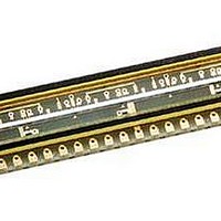
... Output Referenced to Ground D Low Image Lag . . . 0.5% Typ D Operation to 5 MHz D Single 5-V Supply Description The TSL210 linear sensor array consists of five sections of 128 photodiodes, associated charge amplifier circuitry, running from a common clock. These sections can be connected to form a contiguous 640 × 1 pixel array. Device pixels measure 120 μ ...
Page 2
... TSL210 640 × 1 LINEAR SENSOR ARRAY TAOS039B − MAY 2007 Terminal Functions TERMINAL I/O I/O NAME NO. AO1 4 O Analog output of section 1. AO2 7 O Analog output of section 2. AO3 11 O Analog output of section 3. AO4 14 O Analog output of section 4. AO5 17 O Analog output of section 5. ...
Page 3
... high impedance state. A 0.1 μF bypass capacitor should be connected between V The LUMENOLOGY r Company 640 × 1 LINEAR SENSOR ARRAY and ground as close as possible to the device www.taosinc.com TSL210 TAOS039B − MAY 2007 th clock rising edge, the SO pulse Copyright E 2007, TAOS Inc ...
Page 4
... TSL210 640 × 1 LINEAR SENSOR ARRAY TAOS039B − MAY 2007 † Absolute Maximum Ratings Supply voltage range Input voltage range Input clamp current < Output clamp current Voltage range applied to any output in the high impedance or power-off state Continuous output current Continuous current through V ...
Page 5
... μA O SO5 μ the maximum V sat V out (IL drk IL + 100 V out (white drk = www.taosinc.com TSL210 640 × 1 LINEAR SENSOR ARRAY TAOS039B − MAY 2007 = 640 nm ms, p int MIN TYP MAX UNIT 1.6 2 2.4 0 0.05 0.15 ± 20 ± 0.4% 1 mVrms 155 nJ/cm 2 ...
Page 6
... TSL210 640 × 1 LINEAR SENSOR ARRAY TAOS039B − MAY 2007 Dynamic Characteristics over recommended ranges of supply voltage and operating free-air temperature (see Figure 2) PARAMETER t Analog output settling time to ± CLK SI1 Î Î Î Î Î Î Î Î Î Î Î Î Î Î Î Î Î Î Î Î ...
Page 7
... PHOTODIODE SPECTRAL RESPONSIVITY 25°C A 0.8 0.6 0.4 0.2 0 300 400 500 600 700 800 λ − Wavelength − nm Figure 3 The LUMENOLOGY r Company 640 × 1 LINEAR SENSOR ARRAY TYPICAL CHARACTERISTICS 900 1000 1100 r www.taosinc.com TSL210 TAOS039B − MAY 2007 Copyright E 2007, TAOS Inc ...
Page 8
... The minimum integration time can be calculated from the equation int(min) where: the number of pixels the case of the TSL210, the minimum integration time would be 200 ns int(min important to note that not all pixels will have the same integration time if the clock frequency is varied while data is being output. Copyright E 2007, TAOS Inc. 8 ...
Page 9
... The voltage output is available for the whole period of the clock, so the setup and hold times required for the analog-to-digital conversion must be less than the clock period. The LUMENOLOGY r Company 640 × 1 LINEAR SENSOR ARRAY APPLICATION INFORMATION r www.taosinc.com TSL210 TAOS039B − MAY 2007 Copyright E 2007, TAOS Inc ...
Page 10
... AO1 5 SO1 6 SI2 7 AO2 8 SO2 9 GND 10 SI3 11 AO3 12 SO3 13 SI4 14 AO4 15 SO4 16 SI5 17 AO5 18 SO5 330 Ω Copyright E 2007, TAOS Inc. 10 APPLICATION INFORMATION TSL210 Input Output R L Figure 4. Connection Diagrams r www.taosinc.com PARALLEL CLK 3 SI1 Input 4 AO1 Output 1 5 SO1 6 SI2 7 AO2 ...
Page 11
... NOTES: A. All linear dimensions are in inches (millimeters). B. Pixel centers are located along the center line of the mounting holes. C. Cover glass index of refraction is 1.52. D. This drawing is subject to change without notice. Figure 5. TSL210 Mechanical Specifications The LUMENOLOGY r Company MECHANICAL INFORMATION Pin 1 18 ...
Page 12
... TSL210 640 × 1 LINEAR SENSOR ARRAY TAOS039B − MAY 2007 PRODUCTION DATA — information in this document is current at publication date. Products conform to specifications in accordance with the terms of Texas Advanced Optoelectronic Solutions, Inc. standard warranty. Production processing does not necessarily include testing of all parameters. ...