PT100MF0MP1 Sharp Microelectronics, PT100MF0MP1 Datasheet

Photodetector Transistors PT 15 910nm 3.45mA 1.5Kpcs

PT100MF0MP1

Manufacturer Part Number
PT100MF0MP1
Description
Photodetector Transistors PT 15 910nm 3.45mA 1.5Kpcs
Manufacturer
Sharp Microelectronics
Type
IR Chipr
Datasheets

Specifications of PT100MF0MP1

Maximum Power Dissipation
75 mW
Maximum Dark Current
100 nA
Collector- Emitter Voltage Vceo Max
35 V
Fall Time
6 us
Maximum Operating Temperature
+ 85 C
Minimum Operating Temperature
- 30 C
Rise Time
5 us
Wavelength
940 nm
Transistor Polarity
NPN
Wavelength Typ
910nm
Power Consumption
75mW
Viewing Angle
15°
Transistor Case Style
SMD
No. Of Pins
2
Current Ic Typ
2mA
Half Angle
15°
Nom Sensitivity @ Mw/cm2
2mA @ 1mW / Cm2
Svhc
No SVHC (15-Dec-2010)
Rohs Compliant
Yes
Collector Emitter Voltage Vces
0.4V
Voltage - Collector Emitter Breakdown (max)
35V
Current - Collector (ic) (max)
20mA
Current - Dark (id) (max)
100nA
Power - Max
75mW
Mounting Type
Surface Mount
Orientation
Universal
Package / Case
2-SMD, No Lead
Lead Free Status / RoHS Status
Lead free / RoHS Compliant
Lead Free Status / RoHS Status
Lead free / RoHS Compliant, Lead free / RoHS Compliant

Available stocks

Company
Part Number
Manufacturer
Quantity
Price
Part Number:
PT100MF0MP1
Manufacturer:
SHARP
Quantity:
5 932
Company:
Part Number:
PT100MF0MP1
Quantity:
2 163
Part Number:
PT100MF0MP1N
Manufacturer:
LT
Quantity:
2 480
*1 Max. 10s
PT100M
Series
1. Compact and thin package
2. Surface mount type
3. 2-way mounting : top view/side view
4. Reflow soldering
5. Transparent resin : PT100MC0MP
6. Visible light cut-off resin : PT100MF0MP
1. Touch panels for ATM
2. Touch panels for Car navigation system
3. Touch panels for FA equipment
*1
Notice
Internet Internet address for Electronic Components Group http://sharp-world.com/ecg/
Pair use with GL100MN0MP/GL100MN1MP
is recommended
Collector-emitter voltage
Emitter-collector voltage
Collector current
Collector power dissipation
Operating temperature
Storage temperature
Soldering temperature
Features
Absolute Maximum Ratings
Applications
Parameter
In the absence of confirmation by device specification sheets, SHARP takes no responsibility for any defects that may occur in equipment using any SHARP
devices shown in catalogs, data books, etc. Contact SHARP in order to obtain the latest device specification sheets before using any SHARP device.
Symbol
V
V
x
T
T
T
P
I
CEO
ECO
opr
sol
stg
C
C
0MP
30 to 85
40 to 95
Rating
240
35
20
75
6
(T
a
mW
Unit
mA
˚C
˚C
˚C
V
V
25˚C)
Compact, Surface Mount Type
Phototransistor
Outline Dimensions
Unspecified tolerance: 0.2mm
( ):Reference dimensions
Au-plated area
Pattern example seeing
Please pay attention not to make circuit pattern in
from PCB (Side view)
(0.57)
1.1
(1)
3
1
1.5
1.1
2.8
3
1.5
2
R0.8
(0.57)
(1)
PT100M
Pattern example seeing
from PCB (Top view)
1.1
1.5
1
1
2
2.2
Emitter
Collector
3
x
0MP Series
(Lens center)
1.1
(Unit : mm)
2
area.

Related parts for PT100MF0MP1

PT100MF0MP1 Summary of contents

Page 1

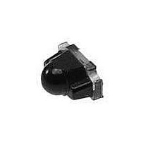
PT100M 0MP x Series Features 1. Compact and thin package 2. Surface mount type 3. 2-way mounting : top view/side view 4. Reflow soldering 5. Transparent resin : PT100MC0MP 6. Visible light cut-off resin : PT100MF0MP Pair use with GL100MN0MP/GL100MN1MP ...

Page 2

Electro-optical Characteristics Parameter PT100MC0MP Collector current PT100MF0MP Collector dark current Collector-emitter saturation voltage Collector-emitter breakdown voltage Emitter-collector breakdown voltage PT100MC0MP Peak sensitivity wavelength PT100MF0MP Rise time Response time Fall time Half intensity angle * E :Irradiance by CIE standard light ...

Page 3

Fig.5 Collector Current vs. Irradiance 100 10 1 0.1 0.01 0.1 Irradiance E (mW/cm e Fig.7 Collector Current vs. Collector-emitter Voltage 5.0 P (max) C 4.5 4 1mW/cm 0.75mW/cm e 3.5 3.0 2.5 0.5mW/cm 2.0 1.5 0.25mW/cm 1.0 ...

Page 4

Fig.11 Radiation Diagram 100 Angular displacement Fig.12 Collector-emitter Saturation Voltage vs. Irradiance 1.4 1.2 1.0 0.8 0.6 1mA 0.4 0.5mA 0.2 I 1mA C ...

Page 5

NOTICE G The circuit application examples in this publication are provided to explain representative applications of SHARP devices and are not intended to guarantee any circuit design or license any intellectual property rights. SHARP takes no responsibility for any problems ...

Related keywords