NSPE561M6.3V10X10.8TR13F NIC Components, NSPE561M6.3V10X10.8TR13F Datasheet
NSPE561M6.3V10X10.8TR13F
Specifications of NSPE561M6.3V10X10.8TR13F


Related parts for NSPE561M6.3V10X10.8TR13F

NSPE561M6.3V10X10.8TR13F Summary of contents
Page 1
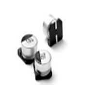
... Tolerance Code M=20% Capacitance Code in µF, fi rst 2 digits are signifi cant Third digit is no. of zeros, “R” indicates decimal for values under 10µF Series ® NIC COMPONENTS CORP. www.niccomp.com Compliant includes all homogeneous materials *See Part Number System for Details 4 ~ 10Vdc LOW ESR COMPONENT 22 ~ 820µ ...
Page 2
... Hybrid Aluminum Electrolytic Capacitors STANDARD VALUES, CASE SIZES & SPECIFICATIONS Part Number NSPE471M4V8X10.8TR13F NSPE681M4V10X10.8TR13F NSPE821M4V10X10.8TR13F NSPE101M6.3V6.3X6.3TR13F NSPE221M6.3V8X10.8TR13F NSPE331M6.3V8X10.8TR13F NSPE391M6.3V8X10.8TR13F NSPE471M6.3V10X10.8TR13F NSPE561M6.3V10X10.8TR13F NSPE220M10V6.3X6.3TR13F NSPE330M10V6.3X6.3TR13F NSPE470M10V6.3X6.3TR13F NSPE101M10V8X10.8TR13F NSPE151M10V8X10.8TR13F NSPE221M10V8X10.8TR13F NSPE331M10V8X10.8TR13F* NSPE331M10V10X10.8TR13F NSPE391M10V10X10.8TR13F NSPE471M10V10X10.8TR13F* *Low temperature refl ow soldering only PEAK TEMPERATURE AND DURATION Diameter/Voltage (120 sec ...