M39003/01-2374 Kemet, M39003/01-2374 Datasheet - Page 2
M39003/01-2374
Manufacturer Part Number
M39003/01-2374
Description
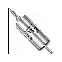
CAP TANT 10UF 50V 10% AXIAL
Manufacturer
Kemet
Series
Military, MIL-PRF-39003, CSR13r
Type
Hermetically Sealedr
Specifications of M39003/01-2374
Tolerance (+ Or -)
10%
Voltage
50VDC
Mounting Style
Through Hole
Polarity
Polar
Construction
Axial
Case Style
Metal
Case Code
Not Required
Lead Spacing (nom)
Not Requiredmm
Df
4%
Dcl
2.5uA
Seal
Hermetic
Insulation
Sleeved
Failure Rate
M
Wire Form
Not Required
Product Length (mm)
17.42mm
Product Height (mm)
Not Requiredmm
Product Depth (mm)
Not Requiredmm
Product Diameter (mm)
7.34mm
Seated Plane Height
Not Requiredmm
Length W/weld (max)
20.88mm
Operating Temp Range
-55C to 125C
Capacitance
10uF
Package / Case
Not Required
Voltage - Rated
50V
Tolerance
±10%
Esr (equivalent Series Resistance)
1.600 Ohm
Operating Temperature
-55°C ~ 125°C
Mounting Type
Through Hole
Size / Dimension
0.289" Dia x 0.686" L (7.34mm x 17.42mm)
Height - Seated (max)
-
Lead Spacing
-
Manufacturer Size Code
C
Features
Military
Lifetime @ Temp.
-
Lead Free Status / RoHS Status
Not Compliant


*Not approved to ‘D’ Failure Rate Level on all voltages and
capacitance values.
**MIL-PRF-39003/10 for space applications.
• CAPACITANCE/VOLTAGE RANGE:
• CAPACITANCE TOLERANCE: Available in stan-
• DISSIPATION FACTOR: Maximum DF limits are
• DC LEAKAGE CURRENT: Each corresponding
• RATED
• IMPEDANCE and ESR: See Application Notes
CSR09
CSR13* Polar-Standard MIL Case
CSS13** Polar-Standard MIL Case
CSR21
CSR23* Polar-Extended Range
.0023-1200µF, 6-125 Volts.
dard EIA values with ±20%, ±10% and ±5% toler-
ances.
shown in corresponding series part number list-
ings on pages 7-41. See Application Notes
Section, page 76 for additional description.
part number table lists maximum leakage current
for each capacitor on pages 7-41. See Application
Notes Section, page 76 for additional description.
SURGE VOLTAGE; REVERSE VOLTAGE: See
Application Notes Section, Pages 76 & 77 for
description.
Section, pages 77 & 78 for description. Reference
ESR values are shown for commercial hermetical-
ly sealed capacitors on page 19.
Polar-Subminiature
Polar-Standard Low ESR
MIL Case
VOLTAGE;
WORKING
T222
T212
T216
T262
T242
D (0.001%/k hrs.)
D (0.001%/k hrs.)
C (0.01%/k hrs.)
D (0.001%/k hrs.)
D (0.001%/k hrs.)
VOLTAGE;
*Not approved to ‘D’ Failure Rate Level on all voltages and
capacitance values.
**MIL-PRF-39003/10 for space applications.
CSR33* Polar-Extended Range
CSS33** Polar-Extended Range
CSR91* Non-Polar
• AC RIPPLE VOLTAGE: Permissible AC ripple volt-
• ENVIRONMENTAL CONSIDERATIONS:
For additional Environmental Test Information see
pages 80, 81 and 82.
• LEAD MATERIAL: Standard leads are solder-coat-
• INSULATING SLEEVES: The standard insulating
• LEAD TAPE and REEL: Reeling per specification
age is related to the ESR of the capacitor and the
power dissipation capabilities of a particular case
size. Thermal capacities for the various case sizes
have been determined empirically and are listed
below. For additional description see page 78.
A. Shock Test: MIL-STD-202, Method 213
B. Thermal Shock, MIL-STD-202,
C. Moisture Resistance: MIL-STD-202,
D. Solderability: MIL-STD-202, Method 208
ed nickel per MIL-STD-1276.
material used in transparent high temperature
plastic, having 2000 volt dielectric strength, excel-
lent dimensional stability and chemical and cold
flow resistance.
RS-296. See pages 71 and 73 for additional infor-
mation.
Method 107, Condition B.
Method 106.
Low Leakage
Low Leakage
A
B
C
D
.09
.100
.125
.180
T252
T256
T213
D (0.001%/k hrs.)
C (0.01%/k hrs.)
D (0.001%/k hrs.)
.070
.090
—
—
5
Related parts for M39003/01-2374
Image
Part Number
Description
Manufacturer
Datasheet
Request
R

Part Number:
Description:
CAP TANT 4.7UF 50V 10% AXIAL
Manufacturer:
Kemet
Datasheet:

Part Number:
Description:
CAP TANT 22UF 35V 10% AXIAL
Manufacturer:
Kemet
Datasheet:
Part Number:
Description:
CAP TANT 10UF 50V 10% AXIAL
Manufacturer:
Kemet
Datasheet:
Part Number:
Description:
CAP TANT 47UF 35V 10% AXIAL
Manufacturer:
Kemet
Datasheet:

Part Number:
Description:
TANTALUM CAP, KEMET # T212A105K050MS
Manufacturer:
Kemet
Datasheet:
Part Number:
Description:
Manufacturer:
Kemet
Datasheet:
Part Number:
Description:
CAP TANT 47UF 35V 10% AXIAL
Manufacturer:
Kemet
Datasheet:
Part Number:
Description:
CAP TANT 22UF 15V 10% AXIAL
Manufacturer:
Kemet
Datasheet:

Part Number:
Description:
CAP, KEMET #F601BL105K250C
Manufacturer:
Kemet
Datasheet:

Part Number:
Description:
T494C226M010ASSOLID TANTALUM CHIP CAPACITORS(T494 SERIES - Low ESR, Industrial Grade)
Manufacturer:
KEMET Kemet Corporation
Datasheet: