Standard Resistance Range
Total Resistance Tolerance .....................................................................10 % or 20 % .................................................5% or 10%
Independent Linearity .............................................................................±5 %...............................................................±5 %
Absolute Minimum Resistance ...............................................................2 ohms maximum........................................... 2 ohms maximum
Effective Electrical Angle ........................................................................(Linear tapers) 240 ° ± 5 °...............................(Linear tapers) 240 ° ± 6 °
Contact Resistance Variation .................................................................±1 %...............................................................±1 % or 3 ohms (whichever is greater)
Dielectric Withstanding Voltage (MIL-STD-202, Method 301)
Insulation Resistance (500 VDC) ............................................................1,000 megohms minimum..............................1,000 megohms minimum
Power Rating (Voltage Limited By Power Dissipation or 350 VAC, Whichever Is Less)
Theoretical Resolution ............................................................................Essentially infinite ...........................................Essentially infinite
Operating Temperature Range ...............................................................-40 °C to +125 °C...........................................-40 °C to +125 °C
Storage Temperature Range...................................................................-55 °C to +125 °C...........................................-55 °C to +125 °C
Temperature Coefficient Over Storage Temperature Range...................±1,000 ppm/°C...............................................±150 ppm/°C
Vibration (Single Section)........................................................................15 G................................................................15 G
Shock (Single Section)............................................................................30 G................................................................30 G
Load Life.................................................................................................1,000 hours ....................................................1,000 hours
Rotational Life (No Load) ........................................................................100,000 cycles ...............................................100,000 cycles
Moisture Resistance (MIL-STD-202, Method 103, Condition B)
IP Rating (Model 96) ...............................................................................IP 65 ...............................................................IP 65
Potentiometer Specifications
Initial Electrical Characteristics
Environmental Characteristics
Linear Tapers (A, B, E, & H) ................................................................(B & E) 1 K ohms to 1 megohm ......................(A & H) 100 ohms to 1 megohm
Audio Tapers (C, D, F, G, S, & T).........................................................(D,G,S, & T) 1 K ohms to 1 megohm ..............(C & F) 1 K ohms to 1 megohm
Sea Level............................................................................................1,500 VAC minimum.......................................1,500 VAC minimum
70,000 Feet ........................................................................................500 VAC minimum..........................................500 VAC minimum
+70 °C Single Section Assembly .......................................................(Linear tapers) 0.5 watt...................................(Linear tapers) 2 watts
+70 °C Multiple Section Assembly.....................................................(Linear tapers) 0.5 watt/section......................(Linear tapers) 1 watt/section
+125 °C ..............................................................................................0 watt..............................................................0 watt
Total Resistance Shift.........................................................................±2 % maximum ..............................................±2 % maximum
Voltage Ratio Shift..............................................................................±5 % maximum ..............................................±5 % maximum
Total Resistance Shift.........................................................................±10 % maximum ............................................±5 % maximum
Total Resistance Shift.........................................................................(Linear tapers) 10 ohms or ±15 % TRS max. ...(All tapers) ±5 % TRS max.
Contact Resistance Variation @ 50,000 cycles ..................................(Linear tapers) ±2 %.......................................±2 %
Total Resistance Shift.........................................................................(Linear tapers) ±10 % TRS maximum ............(All tapers) ±5 % TRS maximum
Insulation Resistance (500 VDC) ........................................................100 megohms minimum.................................100 megohms minimum
(All Others)..........................................................................................IP 40 ...............................................................IP 40
1
1
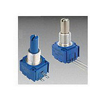
91, 92, 93, 94, 95, 96 - 5/8 ” Square Single-Turn Panel Control
97, 99 - 5/8 ” Square Single-Turn Panel Control with Rotary Switch
Features
■
■
■
■
Available in a variety of pin-out
configurations
Virtually infinite electrical circuit isolation
Model 96 sealed for board wash
Metal or plastic shaft options
Conductive Plastic Element
(Audio tapers) 225 ° ± 5 °
(Audio tapers) 0.25 watt
(Audio tapers) 0.25 watt/section
(whichever is greater)
(Audio tapers) ±20 % maximum
(Audio tapers) ±3 % .......................................±3 %
(Audio tapers) ±20 % TRS maximum
Customers should verify actual device performance in their specific applications.
*RoHS Directive 2002/95/EC Jan 27 2003 including Annex
■
■
DPST and DPDT switch options
RoHS compliant versions available*
Specifications are subject to change without notice.
Cermet Element
(Audio tapers) 225 ° ± 6 °
(Audio tapers) 1 watt
(Audio tapers) 0.5 watt/section