3-87499-2 TE Connectivity, 3-87499-2 Datasheet
3-87499-2
Specifications of 3-87499-2
Available stocks


Related parts for 3-87499-2


3-87499-2 Summary of contents
Page 1
... Material and Finish Housing — Glass-filled thermoplastic, black, 94V-0 rated .140 [3.56] Plating A — Duplex .000030 [0.00076] gold on contact area, .000150-0.000300 [0.00381-0.00762] matte tin on solder area all over .000050 [0.00127] nickel Plating B — Duplex .000010 [0.000254] gold on contact area, .000150-.000300 [0.00381-0.00762] matte tin on solder area all over ...
Page 2
... Material and Finish Housing — Glass-filled thermoplastic, black, 94V-0 rated Contacts — Phosphor bronze, plated as follows: Plating A — Duplex .000030 [0.00076] gold on contact area, .000150-.000300 [0.00381-0.00762] matte tin on solder area all over .000050 [0.00127] nickel Plating B — Duplex .000010 [0.000254] gold on contact area, ...
Page 3
... Plating C — .000150-.000300 [0.00381-0.00762] matte tin on solder leads, all over .000050 [0.00127] nickel for Bottom Entry or Pass Through Applications Related Product Data *±.003 [±0.08] tolerances not to accumulate Mateable Headers — Refer to the Mating Post Selection Guide — page 90 No. of Pos. Performance Characteristics — ...
Page 4
... USA: 1-800-522-6752 South America: 55-11-2103-6000 Canada: 1-905-470-4425 Hong Kong: 852-2735-1628 Mexico: 01-800-733-8926 Japan: 81-44-844-8013 C. America: 52-55-1106-0803 UK: 44-8706-080-208 Plating C ...
Page 5
... PC board); 20 lb. [89 N] maximum insertion force per pair and 10 lb. [44.5 N] minimum extraction force per pair (unsoldered). No tools are required for insertion. 185 South America: 55-11-2103-6000 Hong Kong: 852-2735-1628 Japan: 81-44-844-8013 UK: 44-8706-080-208 ...
Page 6
... Insulation Resistance: 5000 megohms (min.) Mating Force (Receptacle Assemblies): 9.0 oz. [2.50N] (max.) per contact Unmating Force (Receptacle Assemblies): 1.5 oz. [0.42N] (min.) per contact Durability: Tested to 200 cycles (min.) for .000030 [0.00076] gold plated contacts Dimensions are shown for reference purposes only. ...
Page 7
... Notes: 1. Tyco Electronics recommends mating gold or duplex plated headers with duplex plated receptacle assemblies obtain the minimum mating post length, add .020 [0.51] (not including the post lead in chamfer) to the maximum point-of-contact dimension, and ...
Page 8
... Plating C — .000150-.000300 [0.00381-0.00762] matte tin on solder leads, all over .000050 [0.00127] nickel Related Product Data Mateable Headers — Refer to Mating Post Selection Guide — ...
Page 9
... Dual Entry with Holddowns Material and Finish Housing — Glass-filled thermoplastic, black, 94V-0 rated Contacts — Phosphor bronze, plated as follows: Plating A — Duplex .000030 [0.00076] .020 gold on contact area, .000150-.000300 [0.51] [0.00381-0.00762] matte tin on solder Typ. area all over .000050 [0.00127] nickel Plating B — ...
Page 10
... See Note 1 5-147102-5 .800 [20.32] See Note 1 5-147102-7 1.100 [27.94] See Note 1 6-147102-0 1.200 [30.48] See Note 1 6-147102-1 1.400 [35.56] See Note 1 6-147102-3 1.600 [40.64] See Note 1 6-147102-5 1.800 [45.72] See Note 1 6-147102-7 1.900 [48.26] See Note 1 6-147102-8 2.100 [53.34] See Note 1 7-147102-0 2 ...
Page 11
... Material and Finish Typ. Housing — Glass-filled thermoplastic, black, 94V-0 rated Contacts — Phosphor bronze, plated as follows: Plating A — Duplex .000030 [0.00076] .020 [0.51] gold on contact area, .000150-.000300 Typ. [0.00381-0.00762] matte tin on solder area all over .000050 [0.00127] nickel Plating B — ...
Page 12
... USA: 1-800-522-6752 South America: 55-11-2103-6000 Canada: 1-905-470-4425 Hong Kong: 852-2735-1628 Mexico: 01-800-733-8926 Japan: 81-44-844-8013 C. America: 52-55-1106-0803 UK: 44-8706-080-208 Plating C 5-147106-5 5-147106-7 6-147106-0 6-147106-1 6-147106-3 6-147106-5 6-147106-7 6-147106-8 7-147106-0 7-147106-3 ...
Page 13
... ACTION PIN Posts Solder Posts Receptacle Contact (Double Beam with Anti-Overstress) Board Retention Feature Available 3-Row Header 5-103264-3 5-532956-3 Horizontal Receptacle 6-102589-2 3/4 Shroud, Right Angle Header 5-532956-3 Horizontal Receptacle Dimensions are shown for USA: 1-800-522-6752 reference purposes only. Canada: 1-905-470-4425 Specifications subject Mexico: 01-800-733-8926 to change ...
Page 14
... Performance Specifications Temperature Rating — Headers and Receptacles — Current Rating — –65°C to +125°C (black thermoplastic 3 amperes max. for single contact; housings, 94V-0 rated) 2 amperes max. per contact for fully Durability (Tested to) — 200 cycles energized connector for .000030 [0.00076] gold plating; ...
Page 15
... Notes: 1. .115 [2.92] tail length is for use with .062 [1.57] PC boards; .145 [3.68] tail length is for use with .093 [2.36] PC boards. Notes: 2. Receptacle assemblies with low force contacts are available, consult Tyco Electronics. 3. .256 [6.50] minimum positive pin stop to prevent shorting between rows. ...
Page 16
... Guide Pin Slots and Standoffs) Material and Finish Housing — Glass-filled thermoplastic, black, 94V-0 rated Contacts — Phosphor bronze, duplex plated .000030 [0.00076] gold on contact area, .000050-.000100 [0.00127-0.00254] matte tin on solder area, with entire contact underplated .000050 [0.00127] nickel Related Product Data Mateable Headers — ...
Page 17
... Material and Finish .338 Housing — Glass-filled thermoplastic, [8.59] black, 94V-0 rated .144 Contacts — Phosphor bronze, plated [3.66] .000030 [0.00076] gold in mating area, Dia. Typ. .000050-.000100 [0.00127-0.00254] matte tin on solder area, with entire contact underplated .000050 [0.00127] nickel Related Product Data Mateable Headers — ...
Page 18
... Guide Pins) Material and Finish Housing — Glass-filled thermoplastic, black, 94V-0 rated Posts — Phosphor bronze, plated as follows: Plating A — Duplex plated .000030 [0.00076] gold on contact area, .000100-.000200 [0.00254-0.00508] matte tin on termination end, with entire post underplated .000050 [0.00127] nickel Plating B — ...
Page 19
... Headers with ACTION PIN posts are for use with .093 [2.36] nominal or thicker PC boards. 2. Application tooling for installing headers with ACTION PIN posts is shown on pages 152 and 153. 3. Headers with .250 [6.35] tail length can be made available with make first/break last contacts, consult Tyco Electronics ...
Page 20
... Gold Plate .157 Area) [3.99] .157 .125 [3.99] [3.18] .025 [0.64] Square Board Retention Tails Header Part Nos. with .125 [3.18] Tail Length Standard Solder Tails Board Retention Tails Plating A Plating B Plating A 6-102802-2 5-102589-8 5-534245-5 6-102802-4 — 5-534245-4 6-102802-5 ...
Page 21
... Material and Finish Housing — Glass-filled thermoplastic, black, 94V-0 rated .210 [5.33] Posts — Phosphor bronze, plated as follows: Plating A — Duplex plated .000030 [0.00076] gold on contact area, .440 .000100-.000200 [0.00254-0.00508] [11.18] matte tin on termination end, with entire post underplated .000050 [0.00127] ...
Page 22
... Ribs, and Latching) Material and Finish Housing — Glass-filled thermoplastic, black, 94V-0 rated Posts — Copper alloy, duplex plated .000030 [0.00076] gold on contact area, .000100-.000200 [0.00254-0.00508] matte tin on termination end, with entire post underplated .000050 [0.00127] nickel Related Product Data Mateable Receptacles — ...
Page 23
... Canada: 1-905-470-4425 Specifications subject Mexico: 01-800-733-8926 to change. C. America: 52-55-1106-0803 .164 [4.17] .059 .350 [1.50] [8.89] Max. .029 [0.74] Dia. 5 .280 [7.11] .059 [1.50] .350 Max. [8.89] .029 [0.74] Dia. 203 South America: 55-11-2103-6000 Hong Kong: 852-2735-1628 Japan: 81-44-844-8013 UK: 44-8706-080-208 ...
Page 24
... For Shrouded Double-Row, 3 and 4 Sided Headers, .100 x .100 [2.54 x 2.54] Centers See Fig. 2 See Fig. 4 Note: Right-angle (Figs. 2 and 3) and “T” (Fig. 1) configurations of barrier insert establish polarization; bar (Fig. 4) configuration of barrier insert compartmentalizes header. Note: All part numbers are RoHS compliant. Dimensions are shown for reference purposes only ...
Page 25
... AMPMODU Interconnection System Accessories: Snap-In Polarizer for Low Profile Headers Material Black thermoplastic, flame retardant Part Numbers 499991-2 (Packaged 50 per bag) 499991-3 (Packaged 1000 per bag) Related Product Data Low Profile Headers used with — pages 135-140 Catalog 1307819 Dimensions are in inches and ...
Page 26
... Right End Open (for stacking to right side) (Page 209) .025 .273/.350* [0.64] [6.93/8.89] Sq. Posts (with housing) USA: 1-800-522-6752 South America: 55-11-2103-6000 Canada: 1-905-470-4425 Hong Kong: 852-2735-1628 Mexico: 01-800-733-8926 Japan: 81-44-844-8013 C. America: 52-55-1106-0803 UK: 44-8706-080-208 .100 x .100 [2.54 x 2.54] ...
Page 27
... Pating A — Selectively plated .000050 [0.00127] gold on contact area, with gold flash over .000050 [0.00127] nickel on entire contact Pating B — Selectively plated .000030 [0.00076] gold on contact area, with gold flash over .000050 [0.00127] nickel on entire contact Pating C — .000100-.000200 [0.00254-0.00508] bright tin over ...
Page 28
... Technical Documents — pages 277, 278 Product Specification 108-36028, 108-36028-1 Application Specification 114-25006 .125 [3.18] centerline single-row, 2 and 3 position housings are available, Base Part No. 104905. They are designed to be stackable end-to-end and side-by-side. Consult Tyco Electronics. 5 Keying Plug Part No. 87179-1 (Plugs directly into housings for .025 [0.64] square post contacts) Material — ...
Page 29
... Stamped 87176-2 — 87133-1 — 87133-7 87133-8 87133-9 1-87133-0 87133-2 87133-5 1-87133-1 1-87133-2 1-87133-3 1-87133-4 1-87133-5 1-87133-6 87133-3 87133-6 87132-1 — 87132-2 87132-5 87132-3 87132-6 87131-1 — 87131-2 87131-5 87131-3 87131-6 209 South America: 55-11-2103-6000 Hong Kong: 852-2735-1628 Japan: 81-44-844-8013 UK: 44-8706-080-208 ...
Page 30
... Values in brackets www.tycoelectronics.com are metric equivalents. AMPMODU Interconnection System Mod IV Wire-Applied Contacts and Housings 1-87631-5 D-R Housing, Polarized with Detent 6-87756-6 Std. Pressure Contacts 102387-1 D-R Ejection Housing, Center Polarized 6-87756-6 Std. Pressure Contacts 1825851-1 Latch 5102154-1 Hdr ...
Page 31
... Plating B — Selectively plated .000015 *For use with AMP-O-LECTRIC Model “K” machines. Call the Technical Support Center (1-800-522-6752) for part nos. [0.00038] gold on contact area, with gold of applicators for use with the AMP-O-LECTRIC Model “G” machines (shown on page 270), as well as other bench flash over ...
Page 32
... Plating E — Selectively plated .000030 [0.00076] gold on contact area, with gold flash over .000050 [0.00127] nickel on entire contact Plating F — Selectively plated .000015 [0.00038] gold on contact area, with gold flash over .000050 [0.00127] nickel on entire contact Plating G — .000100-.000200 [0.00254-0.00508] tin over .000030 [0 ...
Page 33
... Heavy Duty Miniature Applicator for Part Nos. Applicator for Finish AMP-O-LECTRIC Strip Form Loose Piece Machine* Plating A 5-102920-1 5-102920-2 466655-2 Plating E 102918-1 102918-2 Plating A 5-103171-4 5-103171-5 Plating B 5-103171-1 5-103171-2 466571-2 Plating E 102548-5 102548-6 Plating F 102548-1 102548-3 Plating A 2-87195-3 2-87195-6 Plating B 2-87195-4 ...
Page 34
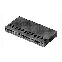
... 2-87499-2 .600 [15.24] 2-87499-3 2-87499-4 .600 [15.24] 2-87499-5 2-87499-6 .700 [17.78] 2-87499-7 2-87499-8 .700 [17.78] 2-87499-9 3-87499-0 .800 [20.32] — 3-87499-2 .800 [20.32] — 3-87499-4 .900 [22.86] — 3-87499-6 .900 [22.86] 3-87499-7 3-87499-8 1.000 [25.40] — 4-87499-0 1.000 [25.40] — 4-87499-2 1.100 [27.94] — ...
Page 35
... Material — Natural color nylon *No marking on housing. Note: Contact Extraction/Lance Reset Tool No. 843996-3. Part No. 87077-2 (Plugs directly into housing) Note: All part numbers are RoHS compliant. Catalog 1307819 Dimensions are in inches and Revised 8-08 millimeters unless otherwise specified. Values in brackets www.tycoelectronics.com are metric equivalents. ...
Page 36
... Notes: 1. Strain reliefs are available and may be purchased separately. Consult Tyco Electronics. Notes: 2. Contact Extraction/Lance Reset Tool No. 843996-3. Note: All part numbers are RoHS compliant. Dimensions are shown for reference purposes only. ...
Page 37
... Notes: 1. Strain reliefs are available and may be purchased separately. Consult Tyco Electronics. Part No. 87077-2 Notes: 2. Contact Extraction/Lance Reset Tool No. 843996-3. (Plugs directly into housing) Note: All part numbers are RoHS compliant. Catalog 1307819 Dimensions are in inches and ...
Page 38
... Notes: 1. The Strain Relief/Pull Tab can be bonded to any thermoplastic connector housing. Notes: 2. Strain reliefs may be purchased separately. Notes: 3. Contact Extraction/Lance Reset Tool No. 843996-3. Note: All part numbers are RoHS compliant. Dimensions are shown for reference purposes only. Specifications subject to change ...
Page 39
... Notes: 1. The Strain Relief/Pull Tab can be bonded to any thermoplastic connector housing. Notes: 2. Strain reliefs may be purchased separately. Notes: 3. Contact Extraction/Lance Reset Tool No. 843996-3. Note: All part numbers are RoHS compliant. Catalog 1307819 Dimensions are in inches and Revised 8-08 millimeters unless otherwise specified ...
Page 40
... This gating feature is not inherent in all production molds. Therefore, the depicted slot will only be present on housings produced on mold tooling requiring this gating feature. Note: Contact Extraction/Lance Reset Tool No. 843996-3. Note: All part numbers are RoHS compliant. Dimensions are shown for reference purposes only ...
Page 41
... Mates with .025 [0.64] ■ square posts ■ Dual cantilever contact beams for reliable matings ■ Locking retention latch provides approximately 3 lb [13. retention force 5-104450-3 MTE Hdr ■ Unique locking latch design helps prevent latch from protruding through latch window Contacts snap into ■ ...
Page 42
... Plating B — Duplex plated .000015 [0.00038] min. gold on contact area, .000050 [0.00127] min. tin in crimp area, with entire contact underplated .000050 [0.00127] min. nickel Plating C — .000100 [0.00254] min. ...
Page 43
... Dimensions are shown for USA: 1-800-522-6752 reference purposes only. Canada: 1-905-470-4425 Specifications subject Mexico: 01-800-733-8926 to change. C. America: 52-55-1106-0803 .600 .036 [15.24] [0.91] 0.72 [1.83] Section X-X 223 South America: 55-11-2103-6000 Hong Kong: 852-2735-1628 Japan: 81-44-844-8013 UK: 44-8706-080-208 5 ...
Page 44
... Material Black thermoplastic, flame retardant, 94V-0 rated Related Product Data Performance Characteristics — page 221 Contacts — page 222 Mateable Headers — pages 104, 105, 135-138 Technical Documents — pages 276-278 Product Specification 108-1472 Application Specification 114-25038 5 224 Catalog 1307819 Dimensions are in inches and ...
Page 45
... Contact Termination Resistance — 15 milliohms (max.) Dielectric Withstanding Voltage — At Sea Level–600 VAC, rms At 70,000 Ft. [21 336 m]–225 VAC, rms Insulation Resistance — 5,000 megohms (min.) Environmental Characteristics Operating Temperature — -65°C to +105°C Vibration — ...
Page 46
... Receptacle Assemblies) 1 Mating AMPMODU Double-Row Shrouded Header Assemblies must have .318 [8.08] mating post length and .150 [3.81] dimension from centerline of last 1 post to inside of end shroud wall. Surface Mount Right-Angle and Vertical Headers are also available (see pages 251 and 252) ...
Page 47
... AMPMODU Interconnection System MTE Interconnection System Wire-to-Wire Pin Assemblies, Shrouded Polarized/Latching (See pages 236 & 237) Receptacle Assemblies, Polarized/Latching (See pages 230 & 231) Receptacle Contact, Insulation Displacement (Used in all Receptacle Assemblies) Crimp Snap-In Receptacle Contact (Used with Unloaded Housings— ...
Page 48
... Note: Insulation displacement contacts 5 accept an insulation diameter of .030 [0.76] min. to .054 [1.37] max. with an insula- tion wall thickness of .015 [0.38] max. Mating post length for preloaded housings is .200 [5.08] min., .250 [6.35] max. Related Product Data Mateable AMPMODU Products Breakaway Headers — ...
Page 49
... Notes: 1. Receptacle assemblies are furnished with strip contacts partially inserted into housing—contacts latched into “preload” windows. Contacts are fully inserted into housings automatically when terminated with Tyco Electronics application machines, or manually when terminated with Tyco Electronics pistol grip hand tool. 2. Use Extraction/Lance Reset Tool No. 843477-1 to remove receptacle contacts. 3. Keying plugs are available, see page 253. ...
Page 50
... Note: Insulation displacement contacts accept an insulation diameter of .030 [0.76] 5 min. to .054 [1.37] max. with an insula- tion wall thickness of .015 [0.38] max. Mating post length for preloaded housings is .200 [5.08] min., .250 [6.35] max. Related Product Data ...
Page 51
... Notes: 1. Receptacle assemblies are furnished with strip contacts partially inserted into housing—contacts latched into “preload” windows. Contacts are fully inserted into housings automatically when terminated with Tyco Electronics application machines, or manually when terminated with Tyco Electronics pistol grip hand tool. 2. Use Extraction/Lance Reset Tool No. 843477-1 to remove receptacle contacts. 3. Keying plugs are available, see page 253. ...
Page 52
... Note: Insulation displacement contacts accept an insulation diameter of .030 [0.76] 5 min. to .054 [1.37] max. with an insula- tion wall thickness of .015 [0.38] max. Mating post length for preloaded housings is .200 [5.08] min., .250 [6.35] max. Related Product Data Coupling Shrouds used with — ...
Page 53
... Tyco Electronics application machines, or manually when terminated with Tyco Electronics pistol grip hand tool. 2. Use Extraction/Lance Reset Tool No. 843477-1 to remove receptacle contacts. 3. Keying plugs are available, see page 253. Note: All part numbers are RoHS compliant. ...
Page 54
... Note: Insulation displacement contacts accept an insulation diameter of .030 [0.76] min. to .054 [1.37] max. with an insulation wall thickness of .015 [0.38] max. Mating post length for preloaded housings is .200 [5.08] min., .250 [6.35] max ...
Page 55
... AMPMODU Interconnection System MTE High Pressure Receptacle Assemblies – Guide Ribs Preassembled housings in strip form are available in positions 2 thru 12. For ease of handling, positions 2 thru 5 are recom- mended when using the Tyco Electronics Manual Pistol Grip Tool. Material and Finish Housing — Thermoplastic, black, 94V-0 rated Contacts — ...
Page 56
... Plating C — .000100 [0.00254] tin over .000050 [0.00127] nickel on entire contact 5 Note: Insulation displacement contacts accept an insulation diameter of .030 [0.76] min. to .054 [1.37] max. with an insula- tion wall thickness of .015 [0.38] max. Related Product Data Mateable AMPMODU Products — Receptacle Assemblies (Polarized/Latching) — ...
Page 57
... Notes: 1. Pin assemblies are furnished with strip contacts partially inserted into housing—contacts latched into “preload” windows. Contacts are fully inserted into housings automatically when terminated with Tyco Electronics application machines, or manually when terminated with Tyco Electronics pistol grip hand tool. 2. Use Extraction/Lance Reset Tool No. 843477-1 to remove pin contacts. Note: All part numbers are RoHS compliant. Catalog 1307819 ...
Page 58
... Note: Insulation displacement contacts 5 accept an insulation diameter of .030 [0.76] min. to .054 [1.37] max. with an insula- tion wall thickness of .015 [0.38] max. Related Product Data Mateable AMPMODU MTE Products (with Pin Assembly Installed in Panel Mount Pin Shroud) — ...
Page 59
... Notes: 1. Pin assemblies are furnished with strip contacts partially inserted into housing—contacts latched into “preload” windows. Contacts are fully inserted into housings automatically when terminated with Tyco Electronics application machines, or manually when terminated with Tyco Electronics pistol grip hand tool. 2. Use Extraction/Lance Reset Tool No. 843477-1 to remove pin contacts. Note: All part numbers are RoHS compliant. Catalog 1307819 ...
Page 60
... Pin Assemblies with Guide Ribs, Installed in Panel Mount Pin Shroud (Refer to pages 238, 239 & 242) Single-Row Coupling Shroud Headers, Polarized/Latching, Straight and Right Angle Post, with or without Holddown (See pages 244-252) USA: 1-800-522-6752 South America: 55-11-2103-6000 ...
Page 61
... Ribs (Refer to pages 232, 233 & 235) 1 Mating AMPMODU Double-Row Shrouded Headers must have .318 [8.08] mating post length and .150 [3.81] dimension from centerline 1 of last post to inside of end shroud wall. Typical Application of Double-Row Coupling Shroud and Mating AMPMODU Products Note: All part numbers are RoHS compliant ...
Page 62
... USA: 1-800-522-6752 South America: 55-11-2103-6000 Canada: 1-905-470-4425 Hong Kong: 852-2735-1628 Mexico: 01-800-733-8926 Japan: 81-44-844-8013 C. America: 52-55-1106-0803 UK: 44-8706-080-208 .250 [6.35] Panel Mount Pin Shroud ...
Page 63
... Application Specification 114-25026 Receptacle Assemblies with Guide Ribs, Installed in Single-Row Coupling Shroud (Refer to pages 232, 233, 235 & 240) Typical Application of Panel Mount Pin Shroud and Mating AMPMODU Products Catalog 1307819 Dimensions are in inches and Revised 8-08 millimeters unless otherwise specified ...
Page 64
... Retention Tails) Recommended PC Board Hole Layout *±.003 [±0.08]; tolerances not to accumulate within one connector pattern. Note: Swaged retention tails are provided in a minimum of two locations per header. Dimensions are shown for reference purposes only. ...
Page 65
... 1.500 [38.10] 1.420 [36.07] 1.300 [33.02] 15 1.600 [40.64] 1.520 [38.61] 1.400 [35.56] 16 1.700 [43.18] 1.620 [41.15] 1.500 [38.10] 17 1.800 [45.72] 1.720 [43.69] 1.600 [40.64] 18 1.900 [48.26] 1.820 [46.23] 1.700 [43.18] 19 2.000 [50.80] 1.920 [48.77] 1.800 [45.72] 20 2.100 [53.34] 2.020 [51.31] 1.900 [48.26 ...
Page 66
... Typ. [8.64±0.08] [2.54] Recommended PC Board Hole Layout (PC board thickness (for Holddown Feature) is .062±.008 [1.57±0.20]) *±.003 [±0.08]; tolerance not to accumulate within one connector pattern. Without Holddown A B .060 [1.52] C .100 Typ. ...
Page 67
... 9 1.000 [25.40] .920 [23.37] .800 [20.32] 10 1.100 [27.94] 1.020 [25.91] .900 [22.86] 11 1.200 [30.48] 1.120 [28.45] 1.000 [25.40] 12 1.300 [33.02] 1.220 [30.99] 1.100 [27.94] 13 1.400 [35.56] 1.320 [33.53] 1.200 [30.48] 14 1.500 [38.10] 1.420 [36.07] 1.300 [33.02] 15 1.600 [40.64] 1.520 [38.61] 1.400 [35.56 ...
Page 68
... Dia. Typ. [1.02±0.08] (for Retention Tails) Recommended PC Board Hole Layout *±.003 [±0.08]; tolerances not to accumulate within one connector pattern. Note: Swaged retention tails are provided in a minimum of two locations per header. Dimensions No. of Pos ...
Page 69
... Typ. Header Profile (Shown for .075±.003 orientation purposes only) [1.90±0.08] Recommended PC Board Hole Layout (Stencil Thickness = .010 [0.25]) *±.003 [±0.08] tolerance not to accumulate within one connector pattern Dimensions A B .300 [7.62] .220 [5.59] .100 [2.54] .400 [10.16] ...
Page 70
... Typ. [1.78±0.51] .035±.003 Dia. Typ. C [0.89±0.08] Plated-Thru Hole Recommended PC Board (Stencil Thickness = .010 [0.25]) *±.003 [±0.08]; tolerance is not to accumulate within one connector pattern. Right-Angle No. of Header Pos. C with Hold Down .100 [2.54] 5-104361-1 14 ...
Page 71
... Typ. Material and Finish Housing — Black thermoplastic, 94V-0 rated Posts — Brass, plated as follows: Plating A — Duplex plated .000030 [.00076] gold on contact area, .000100 [.00254] min. tin on solder area, with entire post underplated .000050 [.00127] nickel. K Plating B — Duplex plated .000015 [ ...
Page 72
... Material and Finish Housing — Black thermoplastic, 94V-0 rated Posts — Brass, plated as follows: Plating A — Duplex plated .000030 [.00076] gold on contact area, .000100 [.00254] min. tin on solder area, with entire post underplated .000050 [.00127] nickel. Plating B — Duplex plated .000015 [ ...
Page 73
... AMPMODU Interconnection System Interchangeable Contacts, Wire Crimp (Snap-In) Material and Finish Short Point Receptacles Copper alloy C7025, plated as follows: Plating A — Duplex plated .000030 [0.00076] min. gold on contact area, .000050 [0.00127] min. tin in crimp area, with entire contact underplated .000050 [0.00127] min. nickel Plating B — ...
Page 74
... Plating B — Duplex plated .000015 [0.00038] gold on contact area, .000030 [0.00076] min. tin on solder area, with entire contact underplated .000050 [0.00127] nickel Plating C — .000100 [0.00254] tin over ...
Page 75
... Header 5-102398-8 D-R Assembly 102396-8 Hermaphroditic Covers Performance Characteristics Contact Current Rating — 3 amperes for single contact in free air. (Amperage could vary due to ambient temperature, wire size and duty cycles.) Operating Temperature — -65°C to +105°C Termination Resistance — 12 milliohms max. ...
Page 76
... Note: Contact Extraction/Lance Reset Tool No. 843477-3, see page 265. Part No. 87077-2 (Plugs directly into housing) Note: All part numbers are RoHS compliant. Dimensions are shown for reference purposes only. Specifications subject to change ...
Page 77
... Instruction Sheet *Cavity identification — first cavity (one side); Tyco Electronics Part No. and date code stamped on housing where size permits. 408-6532 Note: Contact Extraction/Lance Reset Tool No. 843477-3, see page 265. Keying Plugs Part No. 86286-1 (Plugs into receptacle contact) Part No. 87077-2 Material — ...
Page 78
... AMPMODU Interconnection System Low Profile Covers for Double-Row MT Receptacle Assemblies Front Covers A - Polarizing Cover (Mates with AMPMODU 4-sided shrouded headers. Refer to pages 117, 122, 126, 130.) .750 [19.05 Ejection Cover (Mates with AMP-LATCH universal ejection style pin headers equipped with latching ears, Part No ...
Page 79
... Values in brackets www.tycoelectronics.com are metric equivalents Ejection Cover (Mates with AMP-LATCH universal ejection style pin headers equipped with latching ears, Part No. 102185-2 (with push tabs) or Part No. 102312-2 (without push tabs), see Tyco Electronics Catalog 82012. 1.120 Assembled* [28.45] Top View ...
Page 80
... Shields for right-angle headers have integral cantilever beams which provide good contact with the mating shielded MT receptacle assembly, without the use of a separate RF gasket. USA: 1-800-522-6752 South America: 55-11-2103-6000 Canada: 1-905-470-4425 Hong Kong: 852-2735-1628 Mexico: 01-800-733-8926 Japan: 81-44-844-8013 C. America: 52-55-1106-0803 UK: 44-8706-080-208 ...
Page 81
... Related Product Data Double-Row MT Receptacle Assemblies — pages 256, 257 Non-Polarizing Covers (Part No. Series 102541 with back cover 102536 or 102823) — pages 258, 259 Shield Ferrules — page 263 Technical Documents — pages 277, 278 Product Specification 108-25015, 108-25018, 108-25030 Application Specification ...
Page 82
... Related Product Data Double-Row MT Receptacle Assemblies — pages 256, 257 Non-Polarizing Covers (Part No. Series 102541 with back cover 102536 or 102823) — pages 258, 259 Shield Ferrules — page 263 Technical Documents — pages 277, 278 Product Specification 108-25015, 108-25018, 108-25030 Application Specification ...
Page 83
... Notes: 1. Ferrules are used with shielding kits shown on pages 261 & 262, and are purchased separately. 2. Individual anvils and crimpers also may be purchased separately. 3. Ferrule Part Number 1-102903-8 also requires Spacer Part Number 527116-9. Note: All part numbers are RoHS compliant. ...
Page 84
... D ±.003 [±0.08] [2.54±0.08] ±.003 2D [±0.08] Recommended PC Board Hole Layout for 6, 8 and 10 Positions D - Contact centerline is .100 [2.54]; ±.003 [0.08] tolerances not to accumulate within one connector pattern. Dimensions No. of Pos .200 [5.08] .430 [10.92] 8 ...
Page 85
... AWG Application Tooling — 30-26 pages 273-275 26-22 22-20 Technical Documents — Note: Termination tooling for MT receptacle insulation displacement contacts is shown on pages 273-275. pages 277, 278 Product Specification 108-25015, 108-25018, 108-25030 Application Specification 114-25032 Instruction Sheet 408-6532 MT receptacle contacts incorporate the following features ...
Page 86
... Single-row housings can be [3.18] and when used in a converted into double-row housing, they will mate with connectors on .100 x .200 .140 [3.55] long posts. [2.54 x 5.08] centers with These versatile contacts the use of stacking clips ...
Page 87
... Max. A Max. [2.54] .050 .100 [2.54] [1.27] B Spaces @ .100 [2.54 Minimum mating post length is .140 [3.55]. Dimensions A B .200 [5.08] 1 .400 [10.16] 3 .800 [20.32] 7 1.200 [30.48] 11 1.600 [40.64] 15 1.800 [45.72] 17 2.000 [50.80 ...
Page 88
... AMPMODU Interconnection System Mini-Tandem Spring Housings, Double-Row .550 [13.97] A Max. .200 [5.08] .100 [2.54] B Spaces @ .100 [2.54 Minimum mating post length is .140 [3.55]. Dimensions No. of Pos .300 [7.62] 8 .400 [10.16] 12 .600 [15.24] 16 .800 [20.32] Note: Mini-Tandem Spring contacts for use in these housings are shown on page 269. ...
Page 89
... Notes: 1. Mini-Tandem Spring Receptacle Contacts are for use only in the housings shown on pages 267 & 268. They cannot be used in AMPMODU Mod IV Housings. 2. Use Hand Tool No. 91540-1 for crimping loose-piece receptacles to all wire sizes listed above. 3. Application tooling is described on pages 270 & 275. Note: All part numbers are RoHS compliant. Catalog 1307819 ...
Page 90
... By performing maintenance at measured intervals with pre-set limits, operators avoid breakdowns and rejects caused by tool wear or mid-adjustment. For more information, request catalog 1773385. USA: 1-800-522-6752 South America: 55-11-2103-6000 Canada: 1-905-470-4425 Hong Kong: 852-2735-1628 Mexico: 01-800-733-8926 Japan: 81-44-844-8013 C. America: 52-55-1106-0803 UK: 44-8706-080-208 ...
Page 91
... Optional Stripping Module for the AMP 3K/40, AMP 5K/40 and the AMP-O-LECTRIC Model G The combination of the Stripping Module with the AMP-O-LECTRIC Model G Terminator or the AMP ...
Page 92
... Locators are provided with pinned-style die sets for proper contact and wire positioning, and to help minimize contact rota- tion and bending during crimping. Approximate weight 1.3 lb [0.60 kg]. Dimensions are shown for reference purposes only. Specifications subject to change. (Continued) The AMPOMATOR ...
Page 93
... This capability frees the operator’s hands for optimum positioning. Modular Heads: 58062-1 (for MT connectors) 58336-1 (for MTE connectors) 58395-1 (for Level V IDC connectors) 58540-1 (for MTE connectors, discrete wire or flat ribbon cable) Modular Head Tool No. 58540-1 This modular head tool can be used on any pistol grip tool ...
Page 94
... The feed track is a constant force, *At a rate of 13-25 positions at a time. 2700 lb. Power Unit With Cable Notching Die Equipped with a cable notching die an adapter kit, this fully pneumatic bench ...
Page 95
... Termination sequence may include full termination of all contacts, or selective termi- nation. Designed for easy programming, the machine is microprocessor controlled CHAMPOMATOR Model 3A Terminating Machine No. 761420-(*) This floor model machine automatically sorts wires from multiconductor jack- eted cable and terminates them in a user-determined sequence ...
Page 96
... AMPMODU Mod. II Interconnection System, Standard Pressure Receptacle Assembly and Header 108-25027 AMPMODU Mod. II Interconnection System, Short-Point Receptacle Assembly and Header .025 [0.64] Square Posts, Headers, Accessories and Tooling — Pages 92-105, 114-140, 145-153, 163: 108-16 ACTION PIN Contacts 108-25026 AMPMODU Mod. II Interconnection System, Standard Pressure Receptacle ...
Page 97
... They are intended for the Design, Component and Quality Engineers. Locking Clip Contacts and Housings — Pages 206-209: 108-36028 108-36028-1 Connector, Locking Clip, .025 [0.64] Square, Tin Mod. IV Wire-Applied Contacts and Housings — Pages 210-220: 108-25007 108-25019 ...
Page 98
... Tyco Electronics Extraction Tool 843473-1 for AMPMODU Wire-Applied Housings 86308 408-9453 Tyco Electronics Extraction Tools 843996 and 843477 for Removing AMPMODU Crimp Snap-In Receptacle Contacts from Wire-Applied Housings AMPMODU MTE Interconnection System — Pages 225-252: 409-5746 Tyco Electronics Electric Power Unit 931800-1 ...