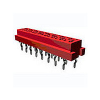
8-215079-2 TE Connectivity, 8-215079-2 Datasheet

8-215079-2
Specifications of 8-215079-2
Available stocks
Related parts for 8-215079-2
8-215079-2 Summary of contents
Page 1
... Electronics personnel, without written authorization from Tyco Electronics Corporation, Harisburg, Pennsylvania USA *Trademark R6-76 (Rev. 07-01) DATE 28/10 /98 APVD M.Gosselink This specification is a controlled document and subject to change. Contact the Engineering Control Organization for the latest revision. 108 - 19052 19/Jun/06 Rev. F DATE 30/10/98 EC EH10-xxxx- LOC H ...
Page 2
... Plate, sheet and strip of wrought copper an copper alloys: mechanical properties 2.3 I.E.C. Specifications I.E.C. 512 Connectors used for frequencies below 3 MHz (Mc/s) I.E.C 68 Basic environmental testing procedures for electric components and electronic equipment. 2.4 EIAJ Specification. RCX-0102/101,102: Test methods of soldering of Surface Mount Devices 3 ...
Page 3
... Wire-to-board and/or Board-to-board connections with the connector system positioned on the solder side of the PC board -for instance Surface Mount Application- • Permanent connections of ribbon cable to PC board, using the Paddle board connector version. • Wire-to board connection with discrete wires. Rev. F R6-77 (Rev. 07-01) 108-19052 Page ...
Page 4
... COSI- cable specification The Micro-MaTch COSI connector is designed for untwisted discrete wires in the range from 20-28 AWG. - Maximum insulation diameter for wires between 20-24 AWG is ∅ 0. Maximum insulation diamter for wires between 24-28 AWG is ∅ 1.27 mm 3.6 ...
Page 5
... SMD Female Top Entry with Male On Wire Paddle board Crimp on Snap In Rev. F R6-77 (Rev. 07-01 Ambient Temperature (°C) Female Top Entry with Male On Board B valid for: Female Top Entry with Male On Wire Female Side Entry with Male On Board SMD inboard with Male On Wire 108-19052 100 105 Page ...
Page 6
... Procedures Visual, dimensional and functional per applicable inspection plan. In acc. with IEC 512-2 test 1a. Magnification acc. with IEC 68-2-20 Test Ta In acc. with: Tyco Test Spec 109-202 Method § 4.3.B. Provisional standards of EIA of JAPAN. RCX-0102/101 ( Test methods of soldering or surface mounting devices) Para 2 ...
Page 7
... In acc. With IEC 912 test 2a Under dry circuit conditions All contacts measured. In acc. With IEC 512-2 test 2a Under dry circuit conditions All contacts measured. Procedures In acc. with IEC 512-8 test 5b. (COSI: 512-8 test15a) Contact retention in housing female connector In acc. with IEC 512-5 test 9a. Page ...
Page 8
... Temperature 105°C Duration: 16 hours. Temperature ° Duration 2 hrs, unmated -40/+105°C 15 min/15 min, 10 cycles mated. 108-19052 In acc with IEC 512-8 Test 16d soldered connector/ cable asembly is loaded with force, perpendicular to board surface In acc. with IEC 512-7 test 13a (COSI 13b) In acc ...
Page 9
... Push-out force in Newtons 108-19052 Paragraph 3.6.1 3.6.8 3.6.22 3.6.21 3.6.24 3.6.22 3.6.8 3.6.1 3.6.1 3.6.16 3.6.8 3.6.16 3.6.13 3.6.10 3.6.8 3.6.21 3.6.8 3.6.10 3.6.1 3.6.1 3.6.8 3.6.25 3.6.8 3.6.17 3.6.8 3.6.1 3.6.1 3.6.2 3.6.1 3.6.1 3.6.3 3.6.1 3.6.1 3.6.14 3.6.25 3.6.14 3 ...
Page 10
... Tests 3. Visual examination Testgroup 8: 1. Visual examination 2. 3. Dry heat under cyclic current loading 4. 5. Visual examination Testgroup 9: 1. Visual examination 2. Pre-conditioning (24 hrs at lab. conditions Voltage proof 5. Climatic sequence a) Dry heat b) Damp heat cyclic, first cycle c) Cold d) Damp Heat cyclic, remaining 5 cycles 6 ...
Page 11
... R6-77 (Rev. 07-01) Termination resistance Termination resistance Push out forces in Newtons Measurements Termination resistance Termination resistance Termination resistance Termination resistance Termination resistance Termination resistance Termination strength in Newtons 108-19052 3.6.1 3.6.18 3.6.1 3.6.1 3.6.9 3.6.22 3.6.9 3.6.1 3.6.1 3.6.12 3.6.1 Paragraph 3.6.1 3.6.11 3.6.23 3 ...
Page 12
... Termination resistance Measurements Termination resistance Insulation resistance Termination resistance Insulation resistance Termination resistance Insulation resistance Termination resistance Termination resistance Termination resistance Termination resistance Termination resistance Termination resistance 108-19052 Paragraph 3.6.1 3.6.19 3.6.20 3.6.1 3.6.1 3.6.11 3.6.22 3.6.11 3.6.1 Paragraph 3.6.1 3.6.10 3 ...
Page 13
... Termination resistance 108-19052 Paragraph 3.6.1 3.6.12 3.6.1 3.6.1 3.6.4 3.6.1 3.6.1 3.6.5 3.6.1 Paragraph 3.6.1 3.6.8 3.6.23 3.6.21 3.6.24 3.6.21 3.6.8 3.6.1 3.6.1 3.6.16 3.6.8 3.6.13 3.6.16 3.6.8 3.6.21 3.6.16 3.6.8 3.6.1 3.6.1 3.6.8 3.6.25 3.6.8 3.6.17 3.6.8 3.6.1 3.6.1 3.6.12 Page ...
Page 14
... Damp heat cyclic, first cycle c) Cold d) Damp Heat cyclic, remaining 5 cycles 5. 6. Voltage proof 7. Visual examination 4. Rev. F R6-77 (Rev. 07-01) Measurements Insulation resistance Insulation resistance 108-19052 Paragraph 3.6.1 3.6.1 3.6.22 3.6.1 3.6.1 3.6.6 3.6.7 3.6.23 3.6.21 3.6.24 3.6.21 3.6.6 3.6.7 3.6.1 ...
Page 15
... At least 5 connectors of the 6 positions or at least 30 contacts shall be used for each testgroup. 4.1.2 Test sequence Qualification inspection shall be verified by testing samples as specified in spec. 108-19052 Par 3.7. 4.2 Requalification testing If changes significantly affecting form, fit or function are made to the product or the manufacturing process, product assurance shall co-ordinate requalification testing, consisting of all or part of the original testing sequence as determined by development/product, quality and reliability engineering ...


