GBU4005 Diodes Inc, GBU4005 Datasheet
GBU4005
Specifications of GBU4005
Available stocks


Related parts for GBU4005


GBU4005 Summary of contents
Page 1
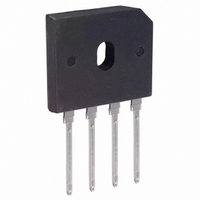
... P 0.76 1.0 All Dimensions in mm GBU GBU GBU GBU GBU Unit 402 404 406 408 410 200 400 600 800 1000 140 280 420 560 700 4.0 150 1.0 5 °C/W 2.2 -55 to +150 GBU4005 - GBU410 ã Diodes Incorporated °C ...
Page 2
... Single half-sine-wave ° 100 1 Fig. 4 Typical Total Capacitance, per element Packaging GBU GBU GBU GBU GBU GBU GBU www.diodes.com ° 0.2 0.6 1.0 1.4 1.8 ° 1.0MHz 10 100 V , REVERSE VOLTAGE (V) R Shipping 20/Tube 20/Tube 20/Tube 20/Tube 20/Tube 20/Tube 20/Tube GBU4005 - GBU410 ...
Page 3
... Diodes Incorporated and all the companies whose products are represented on our website, harmless against all damages. Diodes Incorporated products are not authorized for use as critical components in life support devices or systems without the expressed written approval of the President of Diodes Incorporated. DS21225 Rev IMPORTANT NOTICE LIFE SUPPORT www.diodes.com GBU4005 - GBU410 ...