PB62-F Diodes Inc, PB62-F Datasheet

RECTIFIER BRIDGE 200V 6A PB6

PB62-F

Manufacturer Part Number
PB62-F
Description
RECTIFIER BRIDGE 200V 6A PB6
Manufacturer
Diodes Inc
Datasheet

Specifications of PB62-F

Voltage - Peak Reverse (max)
200V
Current - Dc Forward (if)
6A
Diode Type
Single Phase
Speed
Standard Recovery >500ns, > 200mA (Io)
Mounting Type
Through Hole
Package / Case
PB-6
Lead Free Status / RoHS Status
Lead free / RoHS Compliant
Reverse Recovery Time (trr)
-
Other names
PB62-FDI
Notes:
Features
Mechanical Data
Maximum Ratings and Electrical Characteristics
Ratings at 25° C ambient temperature unless otherwise specified.
Single phase, 60Hz, resistive or inductive load.
DS21310 Rev. 6 - 3
Maximum Recurrent Peak Reverse Voltage
Maximum RMS Bridge Input Voltage
Maximum DC Blocking Voltage
Maximum Average Forward Rectified
Output Current
Peak Forward Surge Current, 8.3ms single half sine-wave
superimposed on rated load (JEDEC Method)
Maximum Forward Voltage Drop per element at 3.0Adc
Maximum dc Reverse Current at rated
dc Blocking Voltage per element
Typical Thermal Resistance
Operating and Storage Temperature Range
Ideal for Printed Circuit Board
Surge Overload Rating of 125A Peak
Low forward Voltage Drop
The Plastic Material Carries U/L Recognition 94V-0
Lead Free Finish, RoHS Compliant (Date Code 0514+) (Note 1)
Case: PB-6, Plastic
Terminals: Leads Solderable per MIL-STD-202, Method 208
Polarity: Symbols Marked on Body
Weight: 4.56 grams
1. EC Directive 2002/95/EC (RoHS) revision 13.2.2003. Glass and High Temperature Solder Exemptions Applied where applicable, see EU Directive
Annex Notes 5 and 7.
Characteristic
@ T
HS
(Heatsink Temp) = 50°C
@ T
@ T
A
A
= 25°C
= 100°C
www.diodes.com
T
Symbol PB605
J
V
V
R
I
I
V
, T
FSM
(AV)
RRM
RSM
V
I
DC
R
F
JC
1 of 3
STG
50
35
50
E
G
D
PB61
100
100
70
+
AC
PB62
H
A
PB605 - PB610
200
140
200
AC
-
-65 to +150
6.0A BRIDGE RECTIFIER
PB64
400
280
400
125
6.0
1.1
10
1
8
A
C
B
PB66
600
420
600
All Dimensions in mm
Dim
G
A
B
C
D
E
H
PB68
800
560
800
Diodes Incorporated
14.73
PB605-PB610
PB-6
3.6Ø
5.84
10.3
Min
1.7
19
PB610 Unit
1.0 Typical
1000
1000
700
15.75
4.0Ø
Max
6.86
11.3
2.7
°C/W
mA
µA
°C
V
V
V
A
A
V

Related parts for PB62-F

PB62-F Summary of contents

Page 1

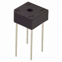
... Max A A 14.73 15. 5.84 6. — D 1.0 Typical E 1.7 2 3.6Ø 4.0Ø H 10.3 11.3 B All Dimensions PB62 PB64 PB66 PB68 PB610 Unit 200 400 600 800 1000 140 280 420 560 700 200 400 600 800 1000 6.0 125 1 °C/W -65 to +150 ...

Page 2

T , HEAT SINK TEMPERATURE (°C) HS Fig. 1, Derating Curve for Output Rectified Current 200 150 100 NUMBER OF CYCLES AT 60Hz Fig. 3, Maximum Forward Surge Current ...

Page 3

... Ordering Information (Note 2) Device PB605 PB61 PB62 PB64 PB66 PB68 PB610 Notes: 2. For Packaging Details our website at http://www.diodes.com/datasheets/ap02007.pdf. Diodes, Inc. and its subsidiaries reserve the right to make changes without further notice to any product herein to make corrections, modifications, enhance- ments, improvements, or other changes. Diodes, Inc. does not assume any liability arising out of the application or use of any product described herein; ...

Related keywords