PTR902-1220F-B103 Bourns Inc., PTR902-1220F-B103 Datasheet - Page 2
PTR902-1220F-B103
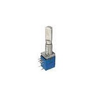
Manufacturer Part Number
PTR902-1220F-B103
Description
Panel Mount Potentiometers 10K LINEAR
Manufacturer
Bourns Inc.
Type
Potentiometerr
Datasheet
1.PTR902-1220F-B103.pdf
(3 pages)
Specifications of PTR902-1220F-B103
Resistance
10kohm
Power Rating
1/20W
Tolerance (+ Or -)
10%
Number Of Turns
1Turn
Technology
Carbon Film
Mounting Style
Through Hole
Termination Style
Pin
Operating Temp Range
-10C to 50C
Failure Rate
Not Required
Shaft Diameter (mm)
6mm
Product Diameter (mm)
Not Requiredmm
Product Height (mm)
11.3mm
Product Depth (mm)
9.5mm
Tolerance
10 %
Taper
Linear
Element Type
Carbon
Shaft Type
Flatted / D
Shaft Length
20 mm
Shaft Diameter
6 mm
Lead Free Status / RoHS Status
Compliant


Applications
■
■
■
■
■
PTR904
RECOMMENDED PCB LAYOUT
Specifi cations are subject to change without notice.
Customers should verify actual device performance in their specifi c applications.
SCHEMATIC
(.197)
(.246)
5.0
6.25
Product Dimensions
(.246)
Audio/TV sets
Automotive sound systems
Amplifi ers/mixers/drum machines/synthesizers/DJ equipment
Multimedia sound systems
Portable electronics
6.25
(.098)
SW
SW
2.5
PTR90 Series - 9 mm Multi-Ganged Potentiometer w/Rotary Switch
SW
(.098)
2.5
2
(.917 ± .020)
R4 R3
23.3 ± 0.5
DIMENSIONS:
R4 R3
R4
3
2
1
3
1
3
2
1
R2 R1
R3
(.197)
3
1
R2 R1
5.0
3
2
1
(.098)
(.197)
2
2.5
5.0
2
(INCHES)
3
2
1
(.197)
(.098)
MM
5.0
2.5
(.014 ± .007)
R2
3
1
M7XP0.75
0.8 ± 0.2
(.039 +.008/-0)
(.197)
DIA. HOLES
5.0
1.0 +0.2/-0
MOUNTING
14 PLCS.
R1
SURFACE
3
1
2
(.197)
PTR906
RECOMMENDED PCB LAYOUT
(.246)
SCHEMATIC
6.25
5.0
SW
(.246)
6.25
SW
(.098)
2.5
2
(.098)
SW
2.5
(.197)
5.0
R6
(.197)
3
1
5.0
R6 R5
R6 R5
(1.213 ± .020)
R5
3
2
1
(.098)
3
1
30.8 ± 0.5
2.5
3
2
1
2
R4 R3
2
R4 R3
3
2
1
(.098)
R4
3
2.5
1
3
2
1
R2 R1
(.197)
R3
5.0
3
1
R2 R1
(.098)
2.5
3
2
1
(.197)
2
5.0
(.197)
3
2
1
2
5.0
(.014 ± .007)
M7XP0.75
(.098)
(.039 +.008/-0)
0.8 ± 0.2
2.5
DIA. HOLES
1.0 +0.2/-0
R2
3
1
20 PLCS.
(.197)
MOUNTING
5.0
SURFACE
R1
3
1
2
(.246)
(.197)
6.25
5.0
PTR908
RECOMMENDED PCB LAYOUT
SCHEMATIC
(.246)
6.25
SW
SW
(.098)
2.5
2
SW
(.098)
2.5
(.197)
5.0
R8
3 3
1 1
R8 R7
(.197)
(.098)
3
2
1
5.0
R8 R7
R7
(.098)
2.5
2.5
3
2
1
2
(1.508 ± .020)
(.197)
5.0
38.3 ± 0.5
2
R6 R5
R6 R5
3
2
1
R6
3 3
1 1
3
2
1
R5
R4 R3
R4 R3
2
(.197)
3
2
1
(.098)
5.0
2
2.5
3
2
1
R2 R1
R4
3 3
(.197)
(.098)
1 1
5.0
2.5
R2 R1
(.098)
R3
2.5
3
2
1
(.197)
5.0
2
(.197)
3
2
1
5.0
(.014 ± .007)
2
(.098)
(.039 +.008/-0)
M7XP0.75
0.8 ± 0.2
2.5
DIA. HOLES
1.0 +0.2/-0
3 3
R2
26 PLCS.
1 1
MOUNTING
(.197)
SURFACE
5.0
R1
2
Related parts for PTR902-1220F-B103
Image
Part Number
Description
Manufacturer
Datasheet
Request
R

Part Number:
Description:
Panel Mount Potentiometers 10K AUDIO
Manufacturer:
Bourns Inc.
Datasheet:
Part Number:
Description:
Panel Mount Potentiometers 100K AUDIO
Manufacturer:
Bourns Inc.
Datasheet:
Part Number:
Description:
PANEL CONTROL
Manufacturer:
Bourns Inc.
Datasheet:
Part Number:
Description:
PANEL CONTROL
Manufacturer:
Bourns Inc.
Datasheet:
Part Number:
Description:
PANEL CONTROL
Manufacturer:
Bourns Inc.
Datasheet:
Part Number:
Description:
PANEL CONTROL
Manufacturer:
Bourns Inc.
Datasheet:
Part Number:
Description:
PANEL CONTROL
Manufacturer:
Bourns Inc.
Datasheet:
Part Number:
Description:
RES,Carbon,20KOhms,50WVDC,20+/-% Tol,6237-Case
Manufacturer:
Bourns Inc.
Datasheet:
Part Number:
Description:
PANEL CONTROL
Manufacturer:
Bourns Inc.
Datasheet:
Part Number:
Description:
PANEL CONTROL
Manufacturer:
Bourns Inc.
Datasheet:

Part Number:
Description:
Manufacturer:
Bourns, Inc.
Datasheet:
Part Number:
Description:
11mm Potentiometer
Manufacturer:
Bourns, Inc.
Datasheet: