SX-550-0700 Silex Technology, SX-550-0700 Datasheet
SX-550-0700
Specifications of SX-550-0700


Related parts for SX-550-0700


SX-550-0700 Summary of contents
Page 1
... SX-550 Embedded Intelligent Module Developer’s Reference Guide Revision L ...
Page 2
... Silex. This publication is subject to change without notice. The software embedded in this SX-550 module includes eCos, the Embedded Configurable Operating System. eCos is licensed under a GNU GPL compatible Free Software License. In compliance with the eCos license, the Silex is offering the eCos source code for this product on our web site at http://www ...
Page 3
...
Page 4
... OEM Interface Electrical Characteristics.........................................................................................................17 Chapter 3 Configuring the SX-550..........................................................................................................................................19 Basic Configuration Requirements......................................................................................................................19 Configuration Methods........................................................................................................................................20 Using the ExtendView Utility to Configure the SX-550 (Ethernet Connection)....................................................21 First-Time IP Address Configuration ..................................................................................................................24 Using a Web Browser to Configure the SX-550..................................................................................................27 Using the Internal Command Console to Configure the SX-550.........................................................................29 Chapter 4 Using the SX-550 with Your Application.................................................................................................................33 Customizing the SX-550 User Interface ...
Page 5
... Chapter 5 Interfacing the SX-550 to the OEM Device.............................................................................................................41 OEM Header Interface........................................................................................................................................43 Antenna Connectors...........................................................................................................................................46 Ethernet PHY......................................................................................................................................................48 Transformer Specification................................................................................................................................48 General Purpose I/O Interface............................................................................................................................49 Power..................................................................................................................................................................50 Chapter 6 Advanced Configuration.........................................................................................................................................51 Factory Default Settings......................................................................................................................................51 Restoring Factory Default Settings..................................................................................................................52 Modifying TCP/IP Settings ................................................................................................................................52 Configuring SNMP..............................................................................................................................................54 Configuring the General Purpose I/O (GPIO) Lines............................................................................................56 Configuring Serial Port Monitor Alert and Trap Configuration ...
Page 6
... Appendix F Silex Contact Information......................................................................................................................................114 Figures Figure 1 SX-550-1701 (left) and SX-550-2701 (right)..............................................................................................4 Figure 2 Installing SX-550 Module in Evaluation Daughtercard (SX-550 WLAN version shown)............................5 Figure 3 SX-550 Module Inserted in Daughtercard (SX-550-1701 WLAN version shown)......................................7 Figure 4 Antenna Connectors..................................................................................................................................7 Figure 5 Optional Serial Signals.............................................................................................................................12 Figure 6 Serial Port DB-9 Connector.....................................................................................................................12 Figure 7 RS-232 Cable Pinouts ...
Page 7
... Table 32 Product Specifications............................................................................................................................74 Table 33 Radio Performance Specifications..........................................................................................................74 Table 34 TCP Port Connections............................................................................................................................77 Table 35 Network Commands...............................................................................................................................82 Table 36 Port Commands......................................................................................................................................89 Table 37 Server Information Commands...............................................................................................................90 Table 38 Service Commands.................................................................................................................................92 Table 39 String Commands...................................................................................................................................94 Table 40 TCP/IP Commands.................................................................................................................................95 Table 41 Power Configuration ..............................................................................................................................99 Part Number 40183-101 Silex SX-550 Developer's Guide Page iv ...
Page 8
... Table 42 Firmware Update..................................................................................................................................100 Table 43 Miscellaneous Commands....................................................................................................................101 Table 44 Antenna Specifications.........................................................................................................................105 Part Number 40183-101 Silex SX-550 Developer's Guide Page v ...
Page 9
... This reference guide provides detailed specifications, diagrams and additional information required to integrate the SX-550 embedded intelligent module in a product. The intended audiences are the developers and engineers responsible for the integration of the module in another product. Safety Precautions To prevent damage to the SX-550 module’s electronic circuit components, follow established ESD practices and procedures for handling static-sensitive devices ...
Page 10
... Part Number 40183-101 Silex SX-550 Developer's Guide Page 2 ...
Page 11
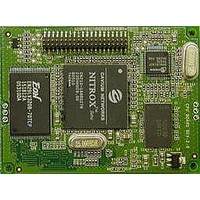
... It can also be used as an Ethernet to 802.11 bridge to enable wireless capabilities on devices that have an Ethernet interface available in two models: SX-550-0700 Ethernet model. The SX-550 Ethernet model consists of a printed circuit board (processor card) that measures 44. 59.70 mm. It includes an embedded processor, auto-sensing 10Base-T/100Base-TX Ethernet MAC/PHY, two UART serial ports (one port is dedicated for use with a console terminal), intelligent power control, and an embedded operating system with a full networking stack and drivers ...
Page 12
... Transmit rate setting supported on the SX-550-1701 and not on the SX-550-2701 AP density (roaming control) supported on the SX-550-1701 and not on the SX-550-2701 WPA group key for link encryption supported on the SX-550-1701 and not on the SX- 550-2701 Blank SSID indicating any SSID OK supported on the SX-550-1701 and not on the SX- 550-2701 To expedite the development process, the SX-550-6900 Evaluation Daughtercard is available ...
Page 13
... The SX-550 Module is installed in the Evaluation Daughtercard as shown in Figure 2. Figure 2 Installing SX-550 Module in Evaluation Daughtercard (SX-550 WLAN version shown) The Evaluation Daughtercard makes it easy to connect to the SX-550 for test and development by providing the following: Two (2) 9-pin connectors and two (2) 10-pin headers for connecting the SX-550 serial ports ...
Page 14
... One (1) 18-pin header for selecting GPIOs as modem controls Verify Development Kit Contents The SX-550-6900 Evaluation Module Development Kit consists of the components listed in Table 1. Please ensure that all materials listed are present and free from visible damage or defects before proceeding. If anything appears to be missing or damaged, please contact SILEX. ...
Page 15
... Figure 3 SX-550 Module Inserted in Daughtercard (SX-550-1701 WLAN version shown you are installing a SX-550 WLAN model, plug the main antenna cable into the Primary Antenna Connector on the card (see picture below). If needed, plug the auxiliary antenna cable into the Auxiliary Antenna Connector ...
Page 16
... If you are installing an SX-550 WLAN model, connect the magnetic antenna base cable to the antenna cable you are installing an SX-550 WLAN model, connect the antenna to the base. 5. Connect one serial null-modem cable from the Serial Port 2 DB-9 connector on the Evaluation Daughtercard to a serial port on a personal computer or laptop. The PC or laptop acts as a console port for command line configuration and monitoring ...
Page 17
... OEM Interface The OEM interface is a 40-pin header that is used to connect the SX-550 module to the SX-550-6900 Evaluation Daughtercard. It will also serve as the primary means of communications between the SX-550 and your OEM device (refer to Chapter 5 for information on using this header to connect with your device) ...
Page 18
... For Manufacturing use only. Do not Connect. Output For Manufacturing use only. Do not Connect. Input For Manufacturing use only. Do not Connect. Output For Manufacturing use only. Do not Connect. Output Power-on Reset (low true) Power Power VCC Input Power Power Ground Silex SX-550 Developer's Guide Page 10 ...
Page 19
... The two serial ports can be accessed with RS-232 signals, via the DB-9 connectors, or logic signals, via the 10-pin headers. Note that serial port 2 is dedicated for use as a console port for configuring the SX- 550. Serial Port 2 is always set for operation at 115.2Kbps, 8 bit character size, no parity, and no flow control ...
Page 20
... Standard serial RS-232 signals are available on the DB-9 connectors J2 and J3 for serial ports 1 and 2, as shown in Figure 6. Figure 6 Serial Port DB-9 Connector Table 6 DB-9 Pinouts for RS-232 Mode Part Number 40183-101 JP3 JP4 JP5 Figure 5 Optional Serial Signals DB-9 RS-232 Signal Silex SX-550 Developer's Guide Page 12 ...
Page 21
... Pin Selectable Signal 1GPIO_1 Via JP3 33.3V 5GPIO_4 Via JP3 7GPIO_5 Via JP3 9GPIO_7 11GPIO_ 8 13GPIO_ Part Number 40183-101 Pin Signal Selectable 2 GPIO_2 Via JP3 4 GPIO_3 Via JP3 6 GND 8 GPIO_6 Via JP3 10 3.3V 12 GPIO_9 14 GND 16 3. Silex SX-550 Developer's Guide Page 13 ...
Page 22
... For Manufacturing use only. Do not Connect. 6/6 mA Ethernet PHY 1 = power down 0 = off (default) 6/6 mA Ethernet PHY 1 = not reset (default reset# I 6/6 mA PCI_LED2YP input I 6/6 mA PCI Power Management Event# input 6/6 mA PCI Clock 1 = clock off 0 = run# (default) Silex SX-550 Developer's Guide Description Page 14 ...
Page 23
... The supplied DB-9 female-to-female null modem cable is wired as shown below. The pinouts are compatible with a standard PC 9-pin serial connector, so this cable can be used to directly connect Serial Port 2 for use as a console terminal to configure the SX-550. It can also be used to connect many types of OEM serial devices to Serial Port 1, provided that these devices use PC-compatible 9-pin connectors ...
Page 24
... The Test Button is normally used either to send configuration information to a printer (button momentarily pressed reset the SX-550 to its default configuration (button held down for more than 5 seconds). ...
Page 25
... GPIO 1 to 10, Reset_N Input Leakage Current Ii Part Number 40183-101 Condition Minimum Maximum 2.0▼ 0.7 Ioh = 4mA 2.4 Iol = 4mA 0.4 Ioh = 6mA 2.4 Iol = 6mA 0.4 0 < Vin < 3.3v -10 +10 Silex SX-550 Developer's Guide Unit Volts Volts Volts Volts Volts Volts A Page 17 ...
Page 26
... Part Number 40183-101 Silex SX-550 Developer's Guide Page 18 ...
Page 27
... IMPORTANT: This chapter assumes that you are either using the SX-550-6900 Evaluation Daughtercard or that you have made the appropriate connections to the SX-550 module OEM Header. Refer to Chapter 2 and Chapter 5 for information on connecting to the SX-550 hardware. This chapter describes the methods for configuring the basic settings of the SX-550, including the IP address, serial port settings, and wireless security ...
Page 28
... These web pages provide an easy-to-use graphical interface for configuring the SX-550. In order to use the internal web pages for the first time, you must assign the SX-550 IP address using some other method (for example, DHCP or arp/ping). This initial IP address assignment need only be done one time ...
Page 29
... Using the ExtendView Utility to Configure the SX-550 (Ethernet Connection) NOTE: Skip this section if you do not have a Windows you do not have an Ethernet connection to the SX-550. The ExtendView Utilty is the easiest way to initially configure the SX-550 from a Windows PC because it allows you to directly set the IP address into an unconfigured SX-550, and it allows you to view the IP addresses of all of the SX-550s on your network ...
Page 30
... Advanced TCP/IP button (refer to Chapter 6 for information). This advanced configuration can be done at a later time, however. NOTE: If you are using DHCP on your network, the SX-550 should have acquired valid IP settings at this point and no further configuration is necessary. However, for some installations, a static IP address is preferred. If your ...
Page 31
... To operate on an 802.11a/b/g network, the SX-550 configuration must be configured with the wireless configuration and security parameters necessary for the SX-550 to communicate over your wireless network (check with your network administrator if you do not know these parameters). Select either Infrastructure (if you ...
Page 32
... NOTE: Skip this section if you have already configured the SX-550 IP address with ExtendView If you are configuring the SX-550 from a non-Windows computer or if you cannot use an Ethernet connection, you must first configure the SX-550 IP address. Note that it is only necessary to perform this Part Number 40183-101 8 ...
Page 33
... SX-550 (skip the remainder of this section you can connect the SX-550 via Ethernet but do not have a DHCP server, then you must use the following procedure for the first-time IP configuration of the SX-550. a. Make sure your PC is connected and has access to your network b ...
Page 34
... If you can connect to an ASCII terminal (such running the HyperTerminal Accessory program) to serial port 2 on the SX-550, you can configure an IP address using the internal command console this, set the terminal to 115.2Kbps, 8-bit characters, no parity, and no flow control. Use the appropriate cable to connect the terminal to serial port 2 (if you are using the Evaluation Daughtercard, the included serial cable will work for many devices). Press < ...
Page 35
... Using a Web Browser to Configure the SX-550 You may skip this section if you have completely configured the SX-550 using ExtendView. However, if you have advanced configuration requirements, such as 802.1X EAP configuration, then you may need to use the internal web pages as described in this section because ExtendView does not support these capabilities. ...
Page 36
... Click the Submit button at the bottom of the window (you may need to scroll) to save your changes. NOTE: If you are using DHCP on your network, the SX- 550 should have acquired valid IP settings at this point and no further configuration is necessary. However, for some installations, a static IP address is preferred. ...
Page 37
... Using the Internal Command Console to Configure the SX-550 You may skip this section if you have completely configured the SX-550 using ExtendView or the SX-550 Internal Web Pages. However, if you are using the bridge mode, you MUST use the Internal Command Console (see Chapter 4 for information on configuring bridge mode ...
Page 38
... IP address manually, enter the following commands: SET IP ADDRESS aa.bb.cc.dd SET IP SUBNET aa.bb.cc.dd SET IP ROUTER aa.bb.cc.dd where aa.bb.cc.dd is the IP address of the SX-550. You can use the command SHOW IP to verify the IP address settings. 3. Enter the basic wireless settings as follows: SET NW SSID <name> ...
Page 39
... IMPORTANT: The console command EXIT must always be used in order to save the changes you made with the internal command Console. 7. After an IP address is configured in the SX-550, you can also access the Internal Command Console in any of the following ways: TELNET. From the Windows Command Prompt (MS-DOS Prompt), Mac OS X Terminal Utility, or UNIX/Linux command line, enter the command: telnet aa ...
Page 40
... Part Number 40183-101 Silex SX-550 Developer's Guide Page 32 ...
Page 41
... Using the SX-550 with Your Application The SX-550 includes a number of capabilities that enable used in a wide range of applications. These capabilities include: 1. User interface customization 2. Power configuration 3. Serial Port Emulator (SPE) software 4. Raw TCP connection 5. RFC2217 6. ECable Mode 7. Print Server mode 8. FTP 9 ...
Page 42
... COM port that functions exactly like the Windows COM1 and COM2 serial ports, except that the I/ O actually goes out over the Ethernet or WLAN to the SX-550 and to the serial device that is connected to the SX-550 result, any application program that uses a standard Windows COM port can also use the Serial Port Emulator ...
Page 43
... You can communicate directly from your application program to the SX-550 using a raw TCP connection. This is done by opening a TCP port on the SX-550 and then sending and receiving data to this port via a socket or equivalent API. This method is more efficient than using the Serial Port Emulator, and does not require any additional software to be installed on your computer ...
Page 44
... RFC 2217 allows you to connect from a host computer over the wireless or Ethernet network to a serial device attached to the serial port of the SX-550, even if the baud rate of that device does not match the baud rate of the host computer’s software. For example, if the host computer software was set to 57.6Kbs and the SX-550 serial port was set to 19.2Kbps, the RFC 2217 support would take care of the mismatch. RFC 2217 also allows you to access your device’ ...
Page 45
... Changing this interval will reduce or increase the amount of network traffic also possible to use UDP instead of TCP for communicating to and from the SX-550. If you wish to use UDP, then: a. Select UDP as ECable I/O Mode. ...
Page 46
... The SX-550 supports FTP binary or ASCII communications. This can be used, for example, to send the contents of a file from device connected to the SX-550 using the FTP protocol. To use FTP, simply enter the standard FTP command from your PC with the IP address of the SX-550 (for example, ftp 192 ...
Page 47
... When an alert occurs, it can be sent as an SNMP trap and/ Email message. The SX-550 also allows the user to set the GPIOs or read the state of the GPIO pins via console commands (console commands can issued through the console port, via the console mode switch feature described earlier in this chapter, via the AT#C command described in Chapter 6, or through TELNET) ...
Page 48
... Bridge Mode The SX-550 can work as a transparent bridge from Ethernet to 802.11a/b/g. This is useful for allowing a device that have an Ethernet interface to be used on a wireless network. Operation is totally transparent, so there is no modification required to the device’s software or firmware. Bridge mode MUST be enabled through the Internal Command Console this, connect to the console as described in Chapter 3 and enter the following commands at the Local> ...
Page 49
... Interfacing the SX-550 to the OEM Device In order to connect the SX-550 module to your device, you will need to provide either a custom daughtercard or a special cable. Both of these solutions will require a 40-pin female connector on one side, with the appropriate connector(s) for connecting to your device’s circuitry on the other side. The custom daughtercard is generally a superior solution because it provides better mechanical connections for greater overall system reliability ...
Page 50
... Part Number 40183-101 Silex SX-550 Developer's Guide Page 42 ...
Page 51
... It includes the necessary pins for serial data I/O, GPIO, and power. Table 12 describes the OEM header interface pinout for the SX-550 module. Table 13 shows the OEM interface signal descriptions. All input and output signals, except the differential signals, are 0 to 3.3V logic signals ...
Page 52
... RESET_N 24 +3.3VDC 8, 14, 27, 33 GND 13, 19, 20, 23, 28, 34, 37, 38 The SX-550 module uses the 40-pin 1.27 mm pitch male header by Gradconn part number BB02-BK401- K03-3040B0. Mating 4.6 mm tall female headers are: Gradconn Interconnect part number: BB02-CL402-K03-000000 www.gradconn.com Samtec part number: SFMC-120-02-S-D www.samtec.com Imperial Connector Systems part number: B2B-401-B-C www ...
Page 53
... E-tec Interconnect part number: BS2-040-H450-11/11AT www.e-tec.ch Part Number 40183-101 Silex SX-550 Developer's Guide Page 45 ...
Page 54
... Figure 23 Using spacers The spacers are installed with the SX-550-0700 Ethernet model as shown below: Figure 24 Using spacers with SX-550 Ethernet model Do not over-tighten the screws during the installation procedure. Although the spacers provide protection against flexing, they can compress or break if too much torque is applied. ...
Page 55
... Nominal Characteristic Impedance Rated Voltage Rated Frequency Contact Resistance Insulation Resistance Antenna Cable Plug For the antenna connector, the SX-550 module uses a Hirose U.FL-R-SMT (CL331-0471-0-01) ultra miniature coaxial receptacle. Mating plugs are: Hirose part number: U.FL-LP-066 www.hirose.co.jp Part Number 40183-101 Description SMT Ultra-miniature Coaxial Connector (U ...
Page 56
... Insertion Loss 1.1 Return Loss -18 -14 -12 Differential to -40 Common Mode -30 Injection Transformer Isolation 1500 Part Number 40183-101 Units Test Conditions H minimum dB maximum 1 to 100 MHz dB minimum MHz dB maximum MHz dB minimum MHz dB maximum MHz dB minimum 60 to 1000 MHz V Silex SX-550 Developer's Guide Page 48 ...
Page 57
... Can be set as input or output I/O 6/6 mA Can be set as input or output 6/6 mA Switch input (Test Button off 0 = switch depressed 6/6 mA LED_1 1= off 0 = illuminated 6/6 mA LED_2 or used as a GPIO 1= off 0 = illuminated 6/6 mA LED_3 or used as a GPIO 1= off Silex SX-550 Developer's Guide Description Page 49 ...
Page 58
... Power is input to the SX-550 Module using the 40-pin OEM Header. Required voltage is 3.3VDC ± 5%. At full power, the current consumption is 900mA (WLAN model) or 628mA (Ethernet model). In low power mode with the processor clock at 60MHz and the SX-550 in power save mode, the current consumption is 370mA. ...
Page 59
... The SX-550 module is equipped with a default configuration that works with most serial-to-Ethernet connections. You can modify the settings to suit your installation requirements. The web browser interface is the recommended method for setting advanced configuration parameters (some of the advanced configuration parameters are not accessible via ExtendView). However, regardless of the method to access the configuration parameters, the method for modifying the parameters is virtually identical ...
Page 60
... ECable UDP mode Restoring Factory Default Settings The factory default settings can restored at any time. If you are using the SX-550 Evaluation Daughtercard, hold down the test button for more than five seconds. If you are not using the evaluation board, short GPIO7 on the OEM header to ground (4.7 K-ohm pull-up resistor connected to +3.3VDC) for more than five seconds ...
Page 61
... Type the new password in the New Password field, then in the Verify Password field. Click OK to change the password or click Cancel to exit. Click Advanced TCP/IP. The Advanced TCP/IP Configuration window displays. Part Number 40183-101 Table 19 TCP/IP Settings Setting Silex SX-550 Developer's Guide Page 53 ...
Page 62
... N : You can configure the same settings using the Web Page configuration. Simply log in using the OTE SX-550 IP address and select TCP/IP. For the changes to become effective, click the Submit button, then reset the SX-550. Configuring SNMP The SX-550 module contains a Simple Network Management Protocol (SNMP) agent that collects and stores management information for network managers using standard SNMP commands ...
Page 63
... This is the only message initiated by the SNMP agent. To configure the SNMP server settings: Log into the SX-550 internal web pages using a standard web browser. Click Server Settings to access the screen shown in Figure 10. You can then enter the relevant SNMP information for your network ...
Page 64
... Click the Submit button to save the changes. You must then restart the SX-550 to make the changes take effect. Configuring the General Purpose I/O (GPIO) Lines The SX-550 module has eight General Purpose I/O (GPIO) lines available for use on connector J7. These GPIO lines are individually programmable for either input, output, or special purpose. By default, six of the GPIO lines are configured for special purpose use ...
Page 65
... Note: <gpio-num> for GPIO_9 and 8 for GPIO_10 (GPIO_7 and GPIO_8 are not settable by the user) NOTE: The direction bit configuration is not changed by a configuration reset to default. Shows current setting of the GPIO direction configuration. Silex SX-550 Developer's Guide Page 57 ...
Page 66
... GPIO_8 is dedicated for a power status LED. The special function bit configuration is not changed by a configuration reset to default. Shows the current setting of the GPIO special function configuration (note that GPIO #7 in this display is actually GPIO_9, while GPIO #8 is actually GPIO_10). Silex SX-550 Developer's Guide Page 58 ...
Page 67
... GPIO signals for general use. NOTE: The special function bit configuration is not changed by a configuration reset to default. This command has no effect on GPIO 1 and 2, which do not have special functions. Shows GPIO special functions control bits as a mask value. Silex SX-550 Developer's Guide Page 59 ...
Page 68
... NOTE: The trigger configuration is not changed by a configuration reset to default. Shows current GPIO trigger conditions. Note that a GPIO may be enabled for two trigger conditions, one for transition, and one for transition GPIO is set for its special function, no trigger is possible on that pin. Silex SX-550 Developer's Guide Page 60 ...
Page 69
... NOTE: Setting the trigger mask resets all undefined trigger strings for triggers that are enabled to the default trigger string value. NOTE: The trigger configuration is not changed by a configuration reset to default. Shows all trigger control bits. Silex SX-550 Developer's Guide 25 24 N/A N/A 17 ...
Page 70
... The remainder of the line is taken as the string for the indicated trigger number. Silex SX-550 Developer's Guide Page 62 ...
Page 71
... NOTE new trigger condition is set, all undefined trigger conditions are reset to their default value. Table 25 GPIO Data Commands Silex SX-550 Developer's Guide Page 63 ...
Page 72
... NOTE: The default output bit value on power up or reset is 0 for all GPIO signals. Shows the current state of the GPIO signals. NOTE: GPIO #7 on this display is actually GPIO_9, while GPIO #8 is actually GPIO_10 Silex SX-550 Developer's Guide Page 64 ...
Page 73
... Table 26 E-GPIO TCP Monitor Commands The E-GPIO TCP monitor allows a computer system to access the SX-550 GPIO pin values. If enabled, this monitor will attempt to make a TCP connection to the remote computer specified. Once connected, the monitor will periodically send the state of the GPIO pins to the remote computer ...
Page 74
... This is an integer representing a bit mask indicating what GPIO pins are available. There for each GPIO pin that is present. For the SX-550, this value is 255 (xFF), indicating 8 GPIO pins. Part Number 40183-101 This message may be optionally sent by the remote computer when an E-GPIO connection is active ...
Page 75
... GPIO trigger condition is disabled. For example a hex value of 4 represents GPIO3 transition (TRIG3) is enabled as a trigger. GPIO transmit string table index Integer read-only gpio.5.1.1.n This value is the index into the GPIO message table for trigger number n. For the SX-550, this always returns n as its value. Part Number 40183-101 ...
Page 76
... GPIO transmit string value Octet-string read-only gpio.5.1.2.n This item returns the GPIO transmit string for trigger number string is defined. The string may be defined even if the corresponding trigger is not currently enabled. Part Number 40183-101 Silex SX-550 Developer's Guide Page 68 ...
Page 77
... Configuring Serial Port Monitor Alert and Trap Configuration The SX-550 module can be configured to scan and compare the data received on the serial port to user- defined strings. A match with a string can be a source for SNMP traps and/or email alerts. The match strings and corresponding email or web page message strings are configured from the Internal Configuration Console interface ...
Page 78
... Setting up Email Alerts and SNMP Traps After you have created the GPIO and/or Serial Port alerts and traps, you can the use the SX-550 internal web pages to set up the recipient Email addresses and/or computer systems. After you have logged into the internal web pages, click Alerts and Traps on the left side of the screen and select either Email Alerts or SNMP IP Traps ...
Page 79
... In command mode data is not passed from the remote computer, so data could be lost if the unit stays in command mode. If the connection cannot be attempted, NO CARRIER status is returned. If the connection attempt fails, NO ANSWER status is returned. If the connection succeeds, CONNECT status is returned. Silex SX-550 Developer's Guide Description Page 71 ...
Page 80
... If console quiet mode is not is enabled, then the response will be the standard console task response. Example: AT#Cset nw ssid silex#Csave AT# response command is given the response is not provided. The default after reset is 1. Silex SX-550 Developer's Guide Description Description Page 72 ...
Page 81
... SX-550 individually. To use this capability: 1. From the ExtendView menu bar, select View and then Multi-Select Mode. 2. The display will change slightly so that there is checkbox by each of the SX-550s listed on the main screen. Click the boxes next to each of the SX-550s that you wish to configure. ...
Page 82
... Differential Quadrature Phase Shift Keying (DQPSK) Differential Binary Phase Shift Keying (DBPSK) IEEE 802.11b and g: Channels and IEEE 802.11a: Channels 36, 40, 44, 48, 52, 56, 60, 64, 149, 153, 157 and 161 54 Mbps with fallback rates of 48, 36, 24, 18, 12, 11 5.5, 2, and 1 Silex SX-550 Developer's Guide Chapter 7 Page 74 ...
Page 83
... Mbps 14 24Mbps 13 36 Mbps 13 48 Mbps 10 54 Mbps 10 6 Mbps 15 9 Mbps 15 12 Mbps 14 18 Mbps 14 24Mbps 13 Silex SX-550 Developer's Guide Typical Maximum Output Output Power Power (dBm) (dBm) 15.5 20.5 15.5 20.5 15.5 20.5 15.5 20.5 17 21.5 17 21.5 15 ...
Page 84
... Part Number 40183-101 36 Mbps 13 48 Mbps 8.5 54 Mbps 8.5 Minimum Typical Receiver Receiver Sensitivity Sensitivity (dBm) -92 -90 -89 -85 -89 -87 -86 -83 -79 -75 -70 -68 -88 -86 -85 -82 -78 -74 -69 -67 Silex SX-550 Developer's Guide 14.8 19 10.9 15 10.9 15 Maximum Receiver Sensitivity (dBm) (dBm) -94 / -92 / -91 / -87 / -91 / -89 / -88 / -85 / -81 / -77 / -72 / ...
Page 85
... TCP Port Connections The SX-550 module supports port connections over TCP/IP using raw TCP ports only. Table 34 describes the TCP ports allocations. Part Number 40183-101 Table 34 TCP Port Connections Port Destination Device 3001 RS-232 9100 RS-232 9200 RFC 2217 Silex SX-550 Developer's Guide ...
Page 86
... There are numerous possible security settings therefore important that you verify the appropriate settings with your network administrator. If you enter the settings incorrectly, the SX-550 will not be able to communicate on your network. The following table summarizes the wireless settings required for each ...
Page 87
... This parameter selects which of the four possible WEP keys will be used as the transmit key (the first key is the default). Select the desired key selection from the pull down menu on the Configure Network Security screen in the SX-550 internal web pages, or use the console command SET NW KEY# n, where ...
Page 88
... The user ID and password must be in the authentication server database. The password may be a text string string of hex bytes. Enter the password on the Configure Network Security screen in the SX- 550 internal web pages, or use the console command SET NW PW <password>, where <password> is the password (default value is anonymous) ...
Page 89
... Organization unit City name State name Country name Key Size (1024 or 2048) You may enter this information on the Configure Private Key page in the internal web pages of the SX- 550 (it cannot be entered via console commands). Part Number 40183-101 Silex SX-550 Developer's Guide Page 81 ...
Page 90
... Signal Strength = 53 Noise Level Part Number 40183-101 Table 35 Network Commands Description WiFi Mode = INFRASTRUCTURE WiFi SSID: silex Speed = 11 Regulatory Domain = 704 WiFi FW Ver = 1F 1.7.1 AP density = LOW TTLS is Disabled WEP is Disabled Link DOWN = 93 = 135 Silex SX-550 Developer's Guide Appendix B Console Commands Page 82 ...
Page 91
... Sets Ethernet wired authentication type The default value is Open System Format ETHAUTH Shows Ethernet wired authentication type Sample output: SET NW AUTHTRY Sets number of times the SX-550 will attempt to authentication The default value is 0. Format AUTHTRY Shows number of authentication tries. Sample output: SET NW CHannel Sets WLAN ad-hoc channel number The valid numbers are 1 through 11 ...
Page 92
... Sets WLAN BSSID to connect to a specific access point’s mac address Format: Part Number 40183-101 Description SET NW KEY# n SET NW KEYVAL <key> SET NW MOde <mode> Wifi mode = AD-HOC (802.11) Radio mode is 802.11b-g SET NW SPeed n Speed = 54 SET NW SSid <name> SSid SET NW BSsid <value> Silex SX-550 Developer's Guide Page 84 ...
Page 93
... TX Single retry frames Multiple retry frames Retry limit exceeded Discards Unicast frames Multicast frames Fragments Unicast octets Multicast octets FCS errors Discards no buffer Discards wrong SA Discards WEP undecr Msg in msg fragments Msg in Bad msg fragments: 0 SET NW CERTCN <name> Silex SX-550 Developer's Guide Page 85 ...
Page 94
... Sets the password for the 802.1x EAP authentication, if enabled The default value is anonymous. Format: Part Number 40183-101 Description Common name 1 SET NW CERTCN2 <name> Common name 2 SET NW CERTEXP <exponent> 65537 (10001h) SET NW CERTKEY <key value> SET NW ID <user id> anonymous@somewhere SET NW PW <password> Silex SX-550 Developer's Guide Page 86 ...
Page 95
... Enable or disable WPA group key mode. If enabled, group keys can be used for data link encryption. The default value is disabled. Format: Part Number 40183-101 Description SET NW INAP [PAP|MSCHAP_V2] Authentication protocol = PAP SET NW REALM <realm> Somewhere SET NW WPAGROUP [ENABLE | DISABLE] WPA-AUTO Enabled WPA-GROUP Disabled. SET NW WPAGROUP [ENABLE | DISABLE] Silex SX-550 Developer's Guide Page 87 ...
Page 96
... Format: Part Number 40183-101 Description SET NW WPAPSK <key> WPA-GROUP Disabled SET NW WPATRACE SET NW WPATRACE nn Disconnect Timer: 5 SET NW DISCONN watchdog timer is disabled 1-255 watchdog timer period in minutes SET NW RESET Silex SX-550 Developer's Guide Page 88 ...
Page 97
... Format: Part Number 40183-101 Table 36 Port Commands Description Port Q-Size Type *S1 0 serial CL PORT S1 JOB SET PORT S1 FLOW <flow> SET PORT S1 Parity <parity> SET PORT S1 SIZE [ SET PORT S1 SPEED <baudrate> SET PORT S1 STOP [ Silex SX-550 Developer's Guide Attributes 115200 XON/XOFF Page 89 ...
Page 98
... DEscription SET SERVEr NAme SET SNMP GETCOMM SET SNMP JETADmin [ ENable | SET SNMP SETCOMM1 <string> SET SNMP SETCOMM2 <string> SET SNMP CONtact SET SNMP LOCation <string> Serial number is 9047595 Silex SX-550 Developer's Guide Sample Output <description-string> <name> <string> DIsable] <string> Page 90 ...
Page 99
... Network Server Enabled Characteristics: Link DOWN SNMP is Enabled serial server Firmware Ver. 4.19 (2004.10.31) Boot Ver. 1.4 16Mbit Flash Silex SX-550 Developer's Guide Sample Output Name: TWC_8A0E2B Frames Sent,1 Collision: 26 Frames Sent, 2+Collision: 5 Send Failures: 0 Send Failure Reasons: 0 Receive Failures: 503 ...
Page 100
... PostScript Tagged Binary Sets filter 1 text replacement match string index. If the index is zero, the default string of <LF> (line feed) is used. The default value is 0. Format: SET SERVI <service name> FRM Sets filter 1 text replacement replace string index. Silex SX-550 Developer's Guide Description Filter nn ...
Page 101
... Format: SET SERVI <service name> TCP Shows the basic parameters for a specific service. If service_num is not provided, parameters for all services are displayed. The command SH SERVI displays the same data as SHOW SERVI SUM. Silex SX-550 Developer's Guide Description nn [ENable | DIsable] <newname> <portname> ...
Page 102
... Table 39 String Commands Description SET STRing <string #> ”value” CL STRing <string #> \1BE 3: \04 4: \1B%-12345X 5: @PJL 6: ENTER LANGUAGE= 7: PCL\0A 8: POSTSCRIPT\0A 9: \FF\04\FF\05\FF\06\FF\07 10: \FF\04\FF\05\FF\06\FF\08 11: \0C # Filter 0 No Filter 1 Text Substitution 2 AppleTalk 3 Text to PostScript 4 PostScript Tagged Binary 5 DC1 Special Silex SX-550 Developer's Guide Page 94 ...
Page 103
... Table 40 TCP/IP Commands Description SET IP ACcess [ ALL] aa.bb.cc.dd {MAsk ee.ff.gg.hh] SET IP RANge [ ALL] aa.bb.cc.dd {MAx ee.ff.gg.hh] All hosts permitted access SET IP ADdress aa.bb.cc.dd SET IP ARP [ENable | DIsable] SET IP BAnner [ENable | DIsable] SET IP CHKSUM [ENable | DIsable] SET IP BOot n Silex SX-550 Developer's Guide Page 95 ...
Page 104
... Description SET IP [ENable | DIsable] SET IP FTIme [ENable | DIsable] SET IP FTP [ENable | DIsable] SET IP HTTP [ENable | DIsable] SET IP KEepalive n SET IP LPD [ENable | DIsable] SET IP MEthod [ AUTO | BOOTP | RARP | DHCP | STATIC ] SET IP PIng aa.bb.cc.dd SET IP PRObe [ENable | DIsable] Silex SX-550 Developer's Guide Page 96 ...
Page 105
... Description SET IP RARp nn nn: 0=both 1=no subnet, SET IP REtry [ENable | DIsable] SET IP ROuter aa.bb.cc.dd SET IP SUbnet aa.bb.cc.dd SET IP TCP [ENable | DIsable] SET IP TELnet [ENable | DIsable] SET IP TFTP [ENable | DIsable ] SET IP Timeout n SET IP WIndow nn Silex SX-550 Developer's Guide 2=no router, 3=neither Page 97 ...
Page 106
... Serial Server: Match string 7 00000080 Serial Server: Match string 8 00000100 undefined 00000200 undefined 00000400 undefined 00000800 undefined 00001000 undefined 00002000 undefined 00004000 undefined 00008000 undefined 00010000 GPIO Trigger1: GPIO1 Silex SX-550 Developer's Guide 3 AUTO 10240 1 min 5 min 9100 3001 Page 98 ...
Page 107
... GPIO Trigger15: GPIO9 80000000 GPIO Trigger16: GPIO10 Description Table 41 Power Configuration Description Sets the power save mode. High power is for fastest throughput, low power is for lowest power consumption. Set POWER LEVEL High Power 1 = Medium Power 2 = Low Power Silex SX-550 Developer's Guide Page 99 ...
Page 108
... Shows the current power control mode. Table 42 Firmware Update Description SET LOAd (ENable | DIsable ] SET LOAd HOst <name> SET LOAd IP aa.bb.cc.dd SET LOAd SOftware <filename> SET LOAd TFTP SET LOAd XModem Firmware load is disabled Load Host IP = 0.0.0.0 Silex SX-550 Developer's Guide Page 100 ...
Page 109
... EXIT command. SH CONSOLE Displays the configured baud rate for the serial console port. SPEED Sample output:: Part Number 40183-101 Description Software file = xxxx.bin Load Host Name = Table 43 Miscellaneous Commands Description Console Speed: 19200 (0) Silex SX-550 Developer's Guide Page 101 ...
Page 110
... For example, when inquiring for various commands to display specific IP parameters, type HELP SHOW IP, or for commands to change specific wireless/network security parameters, type HELP SET NWRK. Part Number 40183-101 Description SET CONSOLE SPEED 19200 115200 Silex SX-550 Developer's Guide 19200 baud 115200 baud Page 102 ...
Page 111
... Part Number 40183-101 Silex SX-550 Developer's Guide Page 103 ...
Page 112
... Antenna Part Number 40183-101 Engineering Drawings Silex SX-550 Developer's Guide Appendix C Page 104 ...
Page 113
... Polarization Electrical Length¼ n Dipole Standard Connector Part Number 40183-101 Table 44 Antenna Specifications Value Dipole Swivel Antenna 2.4 to 5.8 GHz 50 Ohms 2.4 GHz < 1.5 dBi 5.825 GHz < 2.1 dBi 2.0 Omni Vertical SMA male reverse Silex SX-550 Developer's Guide Page 105 ...
Page 114
... Antenna Cable Figure 28 Antenna Cable (Silex Part No. 131-20110-050) Part Number 40183-101 Silex SX-550 Developer's Guide Page 106 ...
Page 115
... There are specific requirements for using the SX-550-2701 modular approval, including: 1. You must put the SX-550 FCC or IC number in a visible location on your product. These numbers are as follows: a. FCC: N6C-SX10WAGIT b ...
Page 116
... FCC Information (SX-550-2701 only) FCC ID: N6C-SX10WAGIT NOTICE In accordance with FCC Part 15, the SX-550-2701 is listed as a Modular Transmitter device. End products that include the SX-550-2701 shall have the words “Contains Transmitter module FCC ID: N6C- SX10WAGIT” exterior label. This equipment complies with Part 15 of the FCC Rules. Operation is subject to the following two conditions: (1) this device may not cause harmful interference, and (2) this device must accept any interference received, including interference that may cause undesired operation ...
Page 117
... RoHS regulations our responsibility to proactively inform our customers if we identify a potential risk of breaching the regulations in our product. 1. Product information: Silex product P/N: SX-550-0700, SX-550-1701, SX-550-2701, SX-550-6900 Silex description: Intelligent module 2. Classification: Full compliance with RoHS requirements (7/7)(Pb, HG, CR ...
Page 118
... Part Number 40183-101 Silex SX-550 Developer's Guide Page 110 ...
Page 119
... Occasionally it may be necessary to update the SX-550 to take advantage of new features or to fix specific problems. The simplest way to perform this update is with the Silex UpdateIP utility for Windows XP and 2000 computers. This utility can be found on the CD-ROM that is included with the SX-550 can be downloaded from the Support & Downloads section of the Silex website (www ...
Page 120
... If you are using a different operating system, please refer to the documentation of that operating system for information on how to use the tftp command. Note that you should specify that the tftp destination file is the Serial Device Server password (“access” by default). Part Number 40183-101 Silex SX-550 Developer's Guide Page 112 ...
Page 121
... Tel: +49-2159-67500 Tel: 0800-7453938 German toll free Email: contact@silexeurope.com Silex Technology Beijing, Inc. www.silex.com.cn Tel: +86-10-8497-1430 Email: contact@silex.com.cn Corporate Headquarters Silex Technology, Inc. www.silex.jp Tel: +81-6-6730-3751 Email: support@silex.jp Part Number 40183-101 Silex Contact Information Silex SX-550 Developer's Guide Appendix F Page 113 ...
Page 122
... Part Number 40183-101 silex technology america, Inc. www.silexamerica.com Silex SX-550 Developer's Guide Page 114 ...