V600HS61 2M Omron, V600HS61 2M Datasheet - Page 9
V600HS61 2M
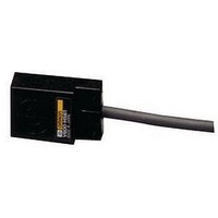
Manufacturer Part Number
V600HS61 2M
Description
RFID Modules & Development Tools R/W HEAD W/2M CABLE
Manufacturer
Omron
Datasheet
1.V600A62R_10M.pdf
(15 pages)
Specifications of V600HS61 2M
For Use With
V600 RFID
Lead Free Status / RoHS Status
Lead free / RoHS Compliant


Power Supply Voltage
Do not impose any voltage exceeding the rated voltage range. Doing
so, or applying alternating current (100 VAC) may cause the product
to explode or burn.
Load Short-circuiting
Do not short-circuit the load connected to the product or connect to
the power supply. Doing so may cause the product to explode or
burn.
Wiring
Avoid wiring mistakes such as incorrect polarity in the power supply.
Wiring mistakes may cause the product to explode or burn.
■ Correct Use
Grounding
The FG line is provided for grounding to the earth. When using the
Amplifier in an environment where it is exposed to large amounts of
noise or if the V600-HA@91/-HA@81/-HA@92 Amplifier malfunctions,
provide a Class-3 ground (ground resistance of 100 Ω or less). Note
that sharing the grounding wire with other equipment or grounding to
the beam of a building will adversely affect the grounding effect.
Mounting
Amplifier Spacing
When installing V600-HA@91/V600-HA@81/V600-HA@92 Amplifi-
ers in a row, provide a minimum space of 10 mm between Amplifiers
in order to prevent them from being affected by the heat produced by
each Amplifier.
When housing the Amplifiers in a box, provide a fan or ventilation
opening for radiating the heat.
When wiring power cables, which carry large current such as motor
drive cables, near the V600-HA@91/81/92 Amplifiers, conduct neces-
sary tests to make sure that the installation conditions are fully satis-
fied.
10
V600-HA 91/81/92
V600-HA 91/81/92
FG
FG
V600-HA 91/81/92
Less than 100 Ω
10 mm min.
OK
NG
Intelligent Flag I/II
Less than 100 Ω
Other equipment
Other equipment
V600-HA
I/O Interface Requirements
1. The TRG input must be 10 ms min.
2. The INHIBIT input must be 20 ms min.
3. Minimum of 5 ms is required as the transfer time of the Read/
4. The read data output must be read after the Normal End Output is
Connecting the Sensor
Hold the black part of the connector, line up the notch and push it in
until it clicks.
Compatibility with the SRAM Memory
Type Data Carrier
1. If the Data Carrier is stationary in the transmission area for a long
2. Use a Data Carrier that has the oscillation frequency of 530 kHz.
Precautions When Using the AUTO
Mode
If transmitting to the Data Carrier while it is traveling under the AUTO
mode, conduct tests to make sure that the travel speed and installa-
tion conditions are fully satisfied.
Write Selection Input (W/R).
set to ON.
time when using the V600-HA@91/81 in the AUTO mode, or when
using the V600-HAR92, it will drastically reduce the battery life.
Therefore, stop the oscillation in the sensor either by turning off
the power of the V600-HA@91/81/92 Amplifier or by setting the
Inhibit input to ON.
Note that the following models manufactured before February
1991 cannot be used.
• V600-D2KR01
• V600-D2KR02
Related parts for V600HS61 2M
Image
Part Number
Description
Manufacturer
Datasheet
Request
R

Part Number:
Description:
RFID Modules & Development Tools 256 BYTE RFID TAG
Manufacturer:
Omron
Datasheet:

Part Number:
Description:
Module, Voltmeter; Volt Meter Meter Type; 3-1/2 Digit LCD; 0.6 in.; 9 VDC
Manufacturer:
Lascar Electronics
Datasheet:

Part Number:
Description:
RFID System Applications
Manufacturer:
Omron
Datasheet:
Part Number:
Description:
Intelligent Flag I
Manufacturer:
Omron
Datasheet:
Part Number:
Description:
Intelligent Flag I/II
Manufacturer:
Omron
Datasheet:
Part Number:
Description:
Rfid System Conforms To Semi Standard, Electromagnetic Inductive 134 Khz
Manufacturer:
Omron Corporation
Datasheet:
Part Number:
Description:
Handheld Reader Writer
Manufacturer:
Omron Corporation
Datasheet:
Part Number:
Description:
Electromagnetic Coupling Rfid System
Manufacturer:
Omron Corporation
Datasheet: