ATAB5283 Atmel, ATAB5283 Datasheet
ATAB5283
Specifications of ATAB5283


Related parts for ATAB5283


ATAB5283 Summary of contents
Page 1
... Tire Pressure Monitoring (TPM). The demonstrator hardware (HW) consists of the LF transmitter board (ATAB5276) patched onto a microcontroller base board and an LF receiver board (ATAB5283). The high antenna driver ability of the transmitter, combined with the sensitive receiver, enables a wake-up distance 2.5 meters. ...
Page 2
... Components Included • ATAB5276 demonstrator board patched onto a microcontroller base board • ATAB5283 receiver board, inclusive Li battery (optionally, the ATAB5282 receiver board) • Antenna module • Serial RS232 interface cable • Two cables for DC power supply • CD-ROM installation software and documentation 2 ...
Page 3
Figure 3-1. Command Settings on the Host Screen 4. Hardware Components 4.1 Transmitter Board ATAB5276_V1 with External Antenna Module Figure 4-1. 4857C–AUTO–07/06 Transmitter Board ATAB5276_V1 ATAK5276-83 3 ...
Page 4
Figure 4-2. The transmitter board (see communicating with a host PC. Operation software must be installed on the host via the enclosed CD-ROM. A power source of typically 12V/2A is used to supply the microcontroller base board and the transmitter ...
Page 5
Figure 4-3. Schematic of the Transmitter Board ATAB5276_V1 4857C–AUTO–07/06 State Machine Gate Driver Control Half Bridge Driver ATAK5276-83 5 ...
Page 6
... SMD 0805 for example, Vishay SMD 0805 for example, Vishay SMD2512 for example, Vishay n.c. EEUFC1H121 Panasonic SMD 0805 Standard SMD SMD 0805 Standard SMD 0805 Standard n. 175781-1 Tyco Electronics - Cliff Electronics - - - Atmel 4857C–AUTO–07/06 ® - ® - ® ® ® ...
Page 7
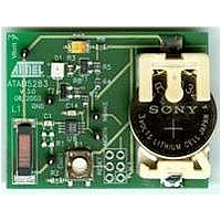
... Received data is indicated by an LED display. Once data is received, the IC can be returned to STANDBY mode by pressing the RESET button. Test pins allow the measurement of all relevant signals lithium battery is used, supplying the receiver with LED indication. Figure 4-4. Figure 4-5. L1 4857C–AUTO–07/06 Receiver Board ATAB5283_V3 Schematic of Receiver Board ATAB5283_V3 LF Receiver VDD 8 COIL1 ...
Page 8
... Table 4-2. Parts List of Receiver Board ATAB5283_V3 Part No. Designation U1 Wake- Transistor T2 Transistor D1 LED L1 Antenna coil C1 Capacitor C1b Capacitor C14 Capacitor C15 Capacitor R1 Resistor R2 Resistor R3 Resistor R4 Resistor R5 Resistor R6 Resistor R7 Resistor R8 Resistor Vbatt1 Battery holder Li-Cell - S1 Push button 6 pcs Test pins 4.4 Receiver Board ATAB5282 An LF wake-up demonstration can alternatively be performed with the 3D receiver ATA5282. Due to the header detection, the Q-factor of the antenna module has to be reduced to Q < ...
Page 9
Figure 4-6. Figure 4- 4857C–AUTO–07/06 Receiver Board ATAB5282_V4 Schematic of Receiver Board ATAB5282_V4 R1 C1a C1b COIL1 1 VDD COIL1 R2 ATA5282 C2b C2a COIL2 NWAKE/ 2 COIL2 DATA R3 C3a C3b COIL3 3 COIL3 NSCL TSSOP8 ...
Page 10
... 100 k 100 100 3V/ 220 mAh - pole Type Manufacturer ATA5282 Atmel BC857 TLMT3100 Vishay 3DC1515S-0477X Predan SMD Ceramic for example, Vishay SMD Ceramic for example, Vishay SMD Ceramic for example, Vishay Tantalum for example, Vishay Tantalum for example, Vishay SMD 0805 ...
Page 11
Demonstrator: Getting Started 1. Build up the demonstrator system according to the configuration shown in page 2. Install the demonstration software by executing setup.exe and following the menu instructions. If, during the installation process, the proposed default folder is ...
Page 12
... Protocol Sent Indicated by LED on Receiver Board 1. After starting the demonstrator, insert the battery into the slot of the ATAB5283/ATAB5282 receiver board and place the board within a distance of about the ATAB5276, along the transmitter antenna axis. 2. Press the RESET button once to reset the AGC control of the ATA5283 as shown in Figure Figure 6-1 ...
Page 13
... Figure 6-1 on page Send Pattern Whenever the position of the ATAB5283 receiver is moved inside the field, a reset has to be per- formed to re-initialize the AGC control. Do not operate the system near disturbed environments, for example, monitors or SMPS units. The field radiation may negatively influence the system performance ...
Page 14
Error Diagnosis Several parameters are monitored by the IC, such as undervoltage, overtemperature, antenna frequency range, and antenna current. The acknowledge bit is returned by the IC after the pattern has been sent. The status of the acknowledge is ...
Page 15
... Signal Transmission Measurements The relationship of the sent and received protocol can be measured on the boards ATAB5276 (transmitter) and ATAB5283 (receiver) via the related test pins TPx. shows an example of the send protocol with the default data pattern and the default transmitter current of 0.6 Ap. ...
Page 16
... Figure 6-8. A similar protocol transmission to the 3D receiver is shown in Due to the header detection, the Q-factor of the transmitter antenna module is reduced to a value (RANT = 18 ). Figure 6-9. ATAK5276-83 16 Signal Transmission ATAB5276 Transmitter to ATAB5283 Receiver Signal Transmission ATAB5276 Transmitter to ATAB5282 Receiver Figure 6-9. 4857C–AUTO–07/06 ...
Page 17
... Disclaimer: The information in this document is provided in connection with Atmel products. No license, express or implied, by estoppel or otherwise, to any intellectual property right is granted by this document or in connection with the sale of Atmel products. EXCEPT AS SET FORTH IN ATMEL’S TERMS AND CONDI- TIONS OF SALE LOCATED ON ATMEL’S WEB SITE, ATMEL ASSUMES NO LIABILITY WHATSOEVER AND DISCLAIMS ANY EXPRESS, IMPLIED OR STATUTORY WARRANTY RELATING TO ITS PRODUCTS INCLUDING, BUT NOT LIMITED TO, THE IMPLIED WARRANTY OF MERCHANTABILITY, FITNESS FOR A PARTICULAR PURPOSE, OR NON-INFRINGEMENT ...