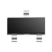
PDTC143TM T/R NXP Semiconductors, PDTC143TM T/R Datasheet - Page 5

PDTC143TM T/R
Manufacturer Part Number
PDTC143TM T/R
Description
Digital Transistors TRANS RET TAPE-7
Manufacturer
NXP Semiconductors
Datasheet
1.PDTC143TM_TR.pdf
(14 pages)
Specifications of PDTC143TM T/R
Configuration
Single
Transistor Polarity
NPN
Typical Input Resistor
4.7 KOhms
Mounting Style
SMD/SMT
Package / Case
SOT-883-3
Collector- Emitter Voltage Vceo Max
50 V
Peak Dc Collector Current
100 mA
Maximum Operating Temperature
+ 150 C
Minimum Operating Temperature
- 65 C
Lead Free Status / RoHS Status
Lead free / RoHS Compliant
Other names
PDTC143TM,315
NXP Semiconductors
THERMAL CHARACTERISTICS
Notes
1. Refer to standard mounting conditions.
2. Reflow soldering is the only recommended soldering method.
3. Refer to SOT883 standard mounting conditions; FR4 with 60 μm copper strip line.
CHARACTERISTICS
T
2004 Aug 06
R
I
I
I
h
V
R1
C
SYMBOL
amb
CBO
CEO
EBO
SYMBOL
FE
CEsat
NPN resistor-equipped transistors;
R1 = 4.7 kΩ, R2 = open
th(j-a)
c
= 25 °C unless otherwise specified.
collector-base cut-off current
collector-emitter cut-off current
emitter-base cut-off current
DC current gain
collector-emitter saturation voltage I
input resistor
collector capacitance
thermal resistance from junction to ambient
SOT54
SOT23
SOT346
SOT323
SOT490
SOT883
SOT416
PARAMETER
PARAMETER
V
V
V
V
V
I
f = 1 MHz
C
E
CB
CE
CE
EB
CE
= i
= 5 mA; I
= 5 V; I
= 50 V; I
= 30 V; I
= 30 V; I
= 5 V; I
e
= 0 A; V
5
CONDITIONS
C
B
C
in free air
note 1
note 1
note 1
note 1
notes 1 and 2
notes 2 and 3
note 1
E
B
B
= 0.25 mA
= 0 A
= 1 mA
CB
= 0 A
= 0 A
= 0 A; T
CONDITIONS
= 10 V;
j
= 150 °C
−
−
−
−
200
−
3.3
−
MIN.
PDTC143T series
VALUE
250
500
500
625
500
500
833
−
−
−
−
−
−
4.7
−
TYP.
Product data sheet
100
1
50
100
−
100
6.1
2.5
MAX.
UNIT
K/W
K/W
K/W
K/W
K/W
K/W
K/W
nA
μA
μA
nA
mV
kΩ
pF
UNIT


