AD10242TZ Analog Devices Inc, AD10242TZ Datasheet - Page 11
AD10242TZ
Manufacturer Part Number
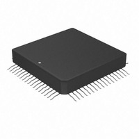
AD10242TZ
Description
IC,A/D CONVERTER,DUAL,12-BIT,HYBRID,QFP,68PIN
Manufacturer
Analog Devices Inc
Datasheet
1.AD10242BZ.pdf
(16 pages)
Specifications of AD10242TZ
Rohs Status
RoHS non-compliant
Number Of Bits
12
Sampling Rate (per Second)
40M
Data Interface
Parallel
Number Of Converters
2
Power Dissipation (max)
2W
Voltage Supply Source
Analog and Digital, Dual ±
Operating Temperature
-55°C ~ 125°C
Mounting Type
Surface Mount
Package / Case
68-CLCC
For Use With
AD10242/PCB - KIT EVAL PCB FOR AD10242
Lead Free Status / RoHS Status
Available stocks
Company
Part Number
Manufacturer
Quantity
Price

Part Number:
AD10242TZ
Manufacturer:
ADI/亚德诺
Quantity:
20 000
Company:
Part Number:
AD10242TZ/883
Manufacturer:
ZCOMM
Quantity:
1 400


If a logic threshold other than the nominal 1.6 V is required,
the following equations show how to use an external resistor,
Rx, to raise or lower the trip point (see Figure 4, R1 = 17 kΩ,
R2 = 8 kΩ).
V
V
While the single-ended encode will work well for many applica-
tions, driving the encode differentially will provide increased
performance. Depending on circuit layout and system noise, a
1 dB to 3 dB improvement in SNR can be realized. It is recom-
mended that the encode signal be ac-coupled into the ENCODE
and ENCODE pins.
The simplest option is shown below. The low jitter TTL signal
is coupled with a limiting resistor, typically 100 Ω, to the primary
side of an RF transformer (these transformers are inexpensive
and readily available; part number in Figures 9 and 10 is from
Mini-Circuits). The secondary side is connected to the ENCODE
and ENCODE pins of the converter. Since both encode inputs
are self-biased, no additional components are required.
REV. C
1
1
=
=
R R
R
1 2
2
Figure 8. Raise Logic Threshold for Encode
+
Figure 9. TTL Source—Differential Encode
5 2
R
+
Figure 7. Lower Threshold for Encode
R
5 2
R Rx
1
TTL
R Rx
R Rx
1
0.01 F
+
1
ENCODE
SOURCE
ENCODE
SOURCE
Rx
+
100
0.01 F
to raise logic threshold.
R Rx
2
R
R
V
AV
T1–1T
x
l
x
V
CC
l
to lower logic threshold.
AD10242
ENCODE
ENCODE
ENCODE
ENCODE
AD10242
ENCODE
ENCODE
AD10242
5V
5V
R1
R2
R1
R2
–11–
If no TTL source is available, a clean sine wave may be substi-
tuted. In the case of the sine source, the matching network is
shown below. Since the matching transformer specified is a 1:1
impedance ratio, the load resistor R should be selected to match
the source impedance. The input impedance of the AD9042
is negligible in most cases.
If a low jitter ECL clock is available, another option is to ac-couple
a differential ECL signal to the encode input pins, as shown
in Figure 11. The capacitors shown here should be chip capaci-
tors but do not need to be of the low inductance variety.
As a final alternative, the ECL gate may be replaced by an ECL
comparator. The input to the comparator could then be a logic
signal or a sine signal.
Care should be taken not to overdrive the encode input pin when
ac-coupled. Although the input circuitry is electrically protected
from overvoltage or undervoltage conditions, improper circuit
operations may result from overdriving the encode input pin.
SOURCE
Figure 10. Sine Source—Differential Encode
SINE
50
Figure 12. ECL Comparator for Encode
Figure 11. Differential ECL for Encode
GATE
ECL
AD96687 (1/2)
510
510
–V
S
T1–1T
510
–V
S
0.1 F
0.1 F
510
0.1 F
0.1 F
R
ENCODE
ENCODE
ENCODE
ENCODE
ENCODE
ENCODE
AD10242
AD10242
AD10242
AD10242
Related parts for AD10242TZ
Image
Part Number
Description
Manufacturer
Datasheet
Request
R

Part Number:
Description:
±1.7g Dual-Axis IMEMS Accelerometer Evaluation Board
Manufacturer:
Analog Devices Inc
Datasheet:

Part Number:
Description:
Inertial Sensor Evaluation System
Manufacturer:
Analog Devices Inc
Datasheet:
Part Number:
Description:
Manufacturer:
Analog Devices Inc
Datasheet:
Part Number:
Description:
Manufacturer:
Analog Devices Inc
Datasheet:
Part Number:
Description:
Manufacturer:
Analog Devices Inc
Datasheet:
Part Number:
Description:
Manufacturer:
Analog Devices Inc
Datasheet:
Part Number:
Description:
Manufacturer:
Analog Devices Inc
Datasheet:
Part Number:
Description:
Manufacturer:
Analog Devices Inc
Datasheet:
Part Number:
Description:
Manufacturer:
Analog Devices Inc
Datasheet:
Part Number:
Description:
Manufacturer:
Analog Devices Inc
Datasheet:
Part Number:
Description:
Manufacturer:
Analog Devices Inc
Datasheet:
Part Number:
Description:
Manufacturer:
Analog Devices Inc
Datasheet:
Part Number:
Description:
Manufacturer:
Analog Devices Inc
Datasheet: