ADIS16300AMLZ Analog Devices Inc, ADIS16300AMLZ Datasheet
ADIS16300AMLZ
Specifications of ADIS16300AMLZ


Related parts for ADIS16300AMLZ


ADIS16300AMLZ Summary of contents
Page 1
FEATURES 14-bit digital gyroscope with digital range scaling ±75°/sec, ±150°/sec, ±300°/sec settings Tri-axis, 14-bit digital accelerometer ±3 g measurement range 13-bit pitch and roll incline calculations 330 Hz bandwidth 150 ms start-up time Factory-calibrated sensitivity, bias, and axial alignment Digitally ...
Page 2
ADIS16300 TABLE OF CONTENTS Features .............................................................................................. 1 Applications ....................................................................................... 1 Functional Block Diagram .............................................................. 1 General Description ......................................................................... 1 Revision History ............................................................................... 2 Specifications ..................................................................................... 3 Timing Specifications .................................................................. 5 Timing Diagrams .......................................................................... 5 Absolute Maximum Ratings ............................................................ 6 ESD ...
Page 3
SPECIFICATIONS T = −40°C to +85°C, VCC = 5.0 V, angular rate = 0°/sec, dynamic range = ±300°/sec, ±1 g, unless otherwise noted. A Table 1. Parameter GYROSCOPE Dynamic Range Initial Sensitivity Sensitivity Temperature Coefficient Misalignment Nonlinearity Initial Bias Error ...
Page 4
ADIS16300 Parameter ADC INPUT Resolution Integral Nonlinearity Differential Nonlinearity Offset Error Gain Error Input Range Input Capacitance DAC OUTPUT Resolution Relative Accuracy Differential Nonlinearity Offset Error Gain Error Output Range Output Impedance Output Settling Time 1 LOGIC INPUTS Input High ...
Page 5
TIMING SPECIFICATIONS T = 25°C, VCC = 5 V, unless otherwise noted. A Table 2. Parameter Description f SCLK t Stall period between data STALL t Read rate READRATE t Chip select to clock edge CS t DOUT valid after ...
Page 6
ADIS16300 ABSOLUTE MAXIMUM RATINGS Table 3. Parameter Acceleration Any Axis, Unpowered Any Axis, Powered VCC to GND Digital Input Voltage to GND Digital Output Voltage to GND Analog Input to GND Operating Temperature Range Storage Temperature Range 1 Extended exposure ...
Page 7
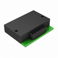
PIN CONFIGURATION AND FUNCTION DESCRIPTIONS INTERFACE TO SYSTEM PCB USING A RIBBON OR FLEX CABLE THAT HAS THE ADIS16300 MATING CONNECTOR INCLUDED. SYSTEM PRINTED CIRCUIT BOARD NOTES ACCELERATION ( , , ) AND ROTATIONAL ( X ...
Page 8
ADIS16300 TYPICAL PERFORMANCE CHARACTERISTICS 0.1 0.01 0.001 0 100 Tau (sec) Figure 7. Gyroscope Allan Variance 0.01 0.001 +1σ MEAN 0.0001 –1σ 0.00001 1k 10k 0.1 Rev Page AXIS X AND Y ...
Page 9
BASIC OPERATION The ADIS16300 is an autonomous sensor system that starts up after it has a valid power supply voltage and begins producing inertial measurement data at a sample rate of 819.2 SPS. After each sample cycle, the sensor data ...
Page 10
ADIS16300 Table 8. User Register Memory Map Name R/W Flash Backup FLASH_CNT R Yes SUPPLY_OUT R No GYRO_OUT R No N/A N/A N/A N/A N/A N/A XACCL_OUT R No YACCL_OUT R No ZACCL_OUT R No TEMP_OUT R No PITCH_OUT R ...
Page 11
OUTPUT DATA REGISTERS Figure 6 provides the positive measurement direction for each inertial sensor (gyroscope and accelerometers). Table 9 provides the configuration and scale factor for each output data register in the ADIS16300. All inertial sensor outputs are 14-bits in ...
Page 12
ADIS16300 Restoring Factory Calibration Set GLOB_CMD[ (DIN = 0xBE02) to execute this function, which resets each user calibration register (see Table 10 and Table 11) to 0x0000, resets all sensor data to zero, and auto- matically updates the ...
Page 13
Dynamic Range There are three dynamic range settings for the gyroscope: ±75°/sec, ±150°/sec, and ±300°/sec. The lower dynamic range settings (±75°/sec and ±150°/sec) limit the minimum filter tap sizes to maintain the resolution as the measurement range decreases. The recommended ...
Page 14
ADIS16300 DIAGNOSTICS Self-Test Self-test offers the opportunity to verify the mechanical integrity of each MEMS sensor. It applies an electrostatic force to each sensor element, which results in mechanical displace- ment that simulates a response to actual motion. Table 1 ...
Page 15
Table 22. ALM_MAG1, ALM_MAG2 Bit Description [15] Comparison polarity 1 = greater than less than [14] Not used [13:0] Data bits that match the format of the trigger source selection Table 23. ALM_SMPL1, ALM_SMPL2 Bit Description [15:8] Not ...
Page 16
... MAX 1.754 END VIEW 1.500 1.246 ORDERING GUIDE Model Temperature Range 1 ADIS16300AMLZ −40°C to +85° RoHS Compliant Part. ©2008–2009 Analog Devices, Inc. All rights reserved. Trademarks and registered trademarks are the property of their respective owners. 13.60 13.50 13.40 2 ...