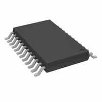
ADV7127KRU140 Analog Devices Inc, ADV7127KRU140 Datasheet - Page 15

ADV7127KRU140
Manufacturer Part Number
ADV7127KRU140
Description
IC,D/A CONVERTER,SINGLE,10-BIT,CMOS,TSSOP,24PIN
Manufacturer
Analog Devices Inc
Datasheet
1.ADV7127JRUZ240.pdf
(16 pages)
Specifications of ADV7127KRU140
Rohs Compliant
NO
Rohs Status
RoHS non-compliant
Settling Time
15ns
Number Of Bits
10
Data Interface
Parallel
Number Of Converters
1
Voltage Supply Source
Single Supply
Power Dissipation (max)
30mW
Operating Temperature
-40°C ~ 85°C
Mounting Type
Surface Mount
Package / Case
24-TSSOP
Number Of Channels
1
Resolution
10b
Interface Type
Parallel
Single Supply Voltage (typ)
3.3/5V
Dual Supply Voltage (typ)
Not RequiredV
Architecture
Segment
Power Supply Requirement
Single
Output Type
Current
Integral Nonlinearity Error
±1LSB
Single Supply Voltage (min)
3V
Single Supply Voltage (max)
5.25V
Dual Supply Voltage (min)
Not RequiredV
Dual Supply Voltage (max)
Not RequiredV
Operating Temp Range
-40C to 85C
Operating Temperature Classification
Industrial
Mounting
Surface Mount
Pin Count
24
Package Type
TSSOP
Lead Free Status / Rohs Status
Not Compliant
Digital Signal Interconnect
The digital signal lines to the ADV7127 should be isolated as
much as possible from the analog outputs and other analog
circuitry. Digital signal lines should not overlay the analog
power plane.
Due to the high clock rates used, long clock lines to the ADV7127
should be avoided so as to minimize noise pickup.
Any active pull-up termination resistors for the digital inputs
should be connected to the regular PCB power plane (V
not the analog power plane.
Analog Signal Interconnect
The ADV7127 should be located as close as possible to the
output connectors thus minimizing noise pickup and reflections
due to impedance mismatch.
REV. 0
CC
), and
–15–
The video output signals should overlay the ground plane, and
not the analog power plane, thereby maximizing the high fre-
quency power supply rejection.
For optimum performance, the analog outputs should each
have a source termination resistance to ground of 75
terminated 75
should be as close as possible to the ADV7127 so as to mini-
mize reflections.
Additional information on PCB design is available in an applica-
tion note entitled “Design and Layout of a Video Graphics
System for Reduced EMI.” This application note is available
from Analog Devices, publication number E1309-15-10/89.
configuration). This termination resistance
ADV7127
(doubly


