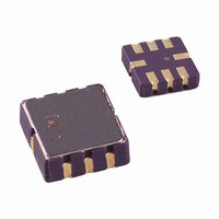
ADXL204CE Analog Devices Inc, ADXL204CE Datasheet

ADXL204CE
Specifications of ADXL204CE
Related parts for ADXL204CE
ADXL204CE Summary of contents
Page 1
FEATURES High performance, dual-axis accelerometer on a single IC chip Specified 3 × × LCC package Better than 2 mg resolution Low power: 500 μA at ...
Page 2
ADXL204 TABLE OF CONTENTS Features .............................................................................................. 1 Applications....................................................................................... 1 General Description ......................................................................... 1 Functional Block Diagram .............................................................. 1 Revision History ............................................................................... 2 Specifications..................................................................................... 3 Absolute Maximum Ratings............................................................ 4 ESD Caution.................................................................................. 4 Pin Configuration and Function Descriptions............................. 5 Typical Performance Characteristics ...
Page 3
SPECIFICATIONS All minimum and maximum specifications are guaranteed. Typical specifications are not guaranteed –40°C to +125° 3 Table 1. Parameter SENSOR INPUT 1 Measurement Range Nonlinearity Package Alignment Error ...
Page 4
ADXL204 ABSOLUTE MAXIMUM RATINGS Table 2. Parameter Acceleration (Any Axis, Unpowered) Acceleration (Any Axis, Powered) Drop Test (Concrete Surface All Other Pins Output Short-Circuit Duration (Any Pin to Common) Temperature Range (Powered) Temperature Range (Storage) Table 4. Profile ...
Page 5
PIN CONFIGURATION AND FUNCTION DESCRIPTIONS Table 5. Pin Function Descriptions Pin No. Mnemonic DNC 3 COM 4 DNC 5 DNC 6 Y OUT 7 X OUT ADXL204E TOP VIEW (Not to Scale ...
Page 6
ADXL204 TYPICAL PERFORMANCE CHARACTERISTICS V = 3.3 V for all graphs, unless otherwise noted VOLTS (V) Figure 4. X-Axis Zero g Bias Output at 25° ...
Page 7
TEMPERATURE (°C) Figure 10. Zero g Bias vs. Temperature—Parts Soldered to PCB 120 130 140 150 160 170 180 ...
Page 8
ADXL204 0.9 0 0.7 0.6 0.5 0.4 0.3 – TEMPERATURE (°C) Figure 16. Supply Current vs. Temperature VOLTS (V) Figure 17. X-Axis Self-Test Response at 25°C ...
Page 9
THEORY OF OPERATION X OUT Y OUT The ADXL204 is a complete acceleration measurement system on a single monolithic IC. The ADXL204 is a dual-axis accelerometer. It contains a polysilicon surface-micromachined sensor and signal conditioning circuitry to implement an open-loop ...
Page 10
ADXL204 APPLICATIONS POWER SUPPLY DECOUPLING For most applications, a single 0.1 μF capacitor, C decouples the accelerometer from noise on the power supply. However in some cases, particularly where noise is present at the 140 kHz internal clock frequency (or ...
Page 11
Peak-to-peak noise values give the best estimate of the uncertainty in a single measurement and is estimated by 6 × rms. Table 8 gives the typical noise output of the ADXL204 for various C and C values. Y Table 8. ...
Page 12
... ADXL204 OUTLINE DIMENSIONS ORDERING GUIDE Model Number of Axes ADXL204CE 2 ADXL204CE-REEL 2 ADXL204EB ©2006 Analog Devices, Inc. All rights reserved. Trademarks and registered trademarks are the property of their respective owners. 1.27 5.00 1. 1.27 4.50 TOP VIEW SQ 1.27 5 0.20 R 0.38 R 0.20 BOTTOM VIEW Figure 23. 8-Terminal Ceramic Leadless Chip Carrier [LCC] ...


