CRD44600-PH-FB Cirrus Logic Inc, CRD44600-PH-FB Datasheet
CRD44600-PH-FB
Specifications of CRD44600-PH-FB


Related parts for CRD44600-PH-FB


CRD44600-PH-FB Summary of contents
Page 1
... W per full-bridge channel into 8 Ω loads using a single +50 V supply (at 1% THD+N). A 155 W unregulated linear power supply is used to power the CRD44600-PH-FB. As shown below, the CS44600 IC takes two stereo digi- tal audio PCM inputs and converts them to PWM outputs ...
Page 2
... Power Supply Ratings ........................................................................................................ 8 3.2 Power Supply Decoupling .................................................................................................. 8 4. ELECTROMAGNETIC INTERFERENCE (EMI) ....................................................................... 9 4.1 Suppression of EMI at the Source ..................................................................................... 9 4.2 EMI Testing ........................................................................................................................ 9 5. CRD44600-PH-FB SCHEMATICS ......................................................................................... 14 6. CRD44600-PH-FB POWER SUPPLY SCHEMATICS ........................................................... 19 7. CRD44600-PH-FB LAYOUT ................................................................................................... 20 8. CRD44600-PH-FB BILL OF MATERIALS 9. TYPICAL PERFORMANCE PLOTS ....................................................................................... 25 10. REVISION HISTORY ............................................................................................................ 30 LIST OF FIGURES Figure 1 ...
Page 3
... Table 1. Bill of Materials................................................................................................................ 23 Table 2. Revision History .............................................................................................................. 30 MAR '05 DS633RD1 CRD44600-PH-FB 3 ...
Page 4
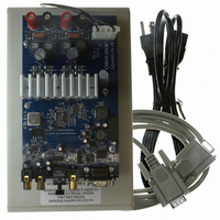
... The CRD44600-PH-FB reference design is an excellent means for evaluating the CS44600 six- channel Class-D PWM modulator. It incorporates a digital Class-D PWM modulator, two full- bridge power stages, and power supply rejection (PSR) circuitry, all on a two-layer board. The CRD44600-PH-FB schematic set is shown in Figures 9 through 13 and the board layout is shown in Figures 15 through 17. 1.1 CS44600 PWM Modulator A complete description of the CS44600 is included in the CS44600 product data sheet ...
Page 5
... Unregulated Linear Power Supply The power supply used for the CRD44600-PH- linear 155 W supply. The supply pro- vides an unregulated +50 V for the TDA8939 power stages. The power supply consists of a transformer, diode bridge rectifier, and bulk capacitor. Schematics are shown in Figure 14. ...
Page 6
... Once the serial port cable is connected between the CRD44600-PH-FB and the host PC, load the FlexLoader.exe from the CRD44600-PH-FB di- rectory. Once loaded, all registers are set to their default reset state. The GUI File menu pro- vides the ability to save and restore (load) register settings ...
Page 7
... Each device is displayed on a separate tab. Register values can be modified bitwise or bytewise. For bitwise, click the appropriate push button for the desired bit. For bytewise, the desired hex value can be typed directly in the register address box in the register map. Figure 2. Advanced Register Debug Tab - CS44600 MAR '05 DS633RD1 CRD44600-PH-FB 7 ...
Page 8
... Figure 3. Advanced Register Debug Tab - CS8416 8 CRD44600-PH-FB MAR '05 DS633RD1 ...
Page 9
... While the PSR functionality of the CS44600 helps reduce power supply noise feedthrough to the output, careful decoupling of the power stage supply rails is essential. Referring to Figure 15, the top side of the CRD44600-PH-FB PWM amplifier board, good decoupling practice is shown. Notice that the 0.1 as physically possible to the power pins of the TDA8939 ...
Page 10
... EMI Testing The CRD44600-PH-FB has been tested to CISPR and FCC Class B limits for radiated and power line conducted emissions. The same test setup and test signal were used for all tests. The setup consisted of an unregulated linear power supply, CRD44600-PH-FB board speaker cable, and two 8-Ω ...
Page 11
... W. The test results shown in Figure 6 and Figure 7 are pre-screened radiated EMI test results from an antenna placement anechoic chamber. The test results shown in Fig- ure 8 are preliminary power line conducted test results. MAR '05 DS633RD1 CRD44600-PH-FB 11 ...
Page 12
... Figure 4. EMI Testing Setup Figure 5. EMI Testing Setup, Close-up CRD44600-PH-FB MAR '05 DS633RD1 ...
Page 13
... Figure 6. Radiated EMI Testing Results- 30 MHz to 200 MHz Figure 7. Radiated EMI Testing Results- 200 MHz to 1 GHz MAR '05 DS633RD1 CRD44600-PH-FB 13 ...
Page 14
... Figure 8. Conducted Power Line Testing Results 14 CRD44600-PH-FB MAR '05 DS633RD1 ...
Page 15
... CRD44600-PH-FB SCHEMATICS MAR '05 DS633RD1 CRD44600-PH-FB 15 ...
Page 16
... CRD44600-PH-FB MAR '05 DS633RD1 ...
Page 17
... MAR '05 DS633RD1 CRD44600-PH-FB 17 ...
Page 18
... CRD44600-PH-FB MAR '05 DS633RD1 ...
Page 19
... MAR '05 DS633RD1 CRD44600-PH-FB 19 ...
Page 20
... CRD44600-PH-FB POWER SUPPLY SCHEMATICS 20 CRD44600-PH-FB MAR '05 DS633RD1 ...
Page 21
... CRD44600-PH-FB LAYOUT MAR '05 DS633RD1 CRD44600-PH-FB 21 ...
Page 22
... CRD44600-PH-FB MAR '05 DS633RD1 ...
Page 23
... MAR '05 DS633RD1 CRD44600-PH-FB 23 ...
Page 24
... CRD44600-PH-FB BILL OF MATERIALS 24 CRD44600-PH-FB MAR '05 DS633RD1 ...
Page 25
... MAR '05 DS633RD1 CRD44600-PH-FB 25 ...
Page 26
... TYPICAL PERFORMANCE PLOTS These performance plots were taken with the CRD44600-PH-FB powered from the described +50 V linear unregulated power supply. The PSR circuitry was calibrated to a nominal +50 V rail. 26 CRD44600-PH-FB MAR '05 DS633RD1 ...
Page 27
... MAR '05 DS633RD1 CRD44600-PH-FB 27 ...
Page 28
... CRD44600-PH-FB MAR '05 DS633RD1 ...
Page 29
... MAR '05 DS633RD1 CRD44600-PH-FB 29 ...
Page 30
... CRD44600-PH-FB MAR '05 DS633RD1 ...
Page 31
... Cirrus Logic, Cirrus, and the Cirrus Logic logo designs are trademarks of Cirrus Logic, Inc. All other brand and product names in this document may be trademarks or service marks of their respective owners. Microsoft Windows is a registered trademark of Microsoft Corporation. MAR '05 DS633RD1 1st Release Table 2. Revision History CRD44600-PH-FB 31 ...
Page 32
... CRD44600-PH-FB MAR '05 DS633RD1 ...