ADNS-2610 Avago Technologies US Inc., ADNS-2610 Datasheet
ADNS-2610
Specifications of ADNS-2610
ADNS-2610


Related parts for ADNS-2610


ADNS-2610 Summary of contents
Page 1
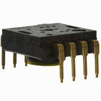
... ADNS-2610 Optical Mouse Sensor Data Sheet Description The ADNS-2610 is a new entry level, small form factor optical mouse sensor used to implement a non- mechanical tracking engine for computer mice. Unlike its predecessor, this new optical mouse sensor allows for more compact and affordable optical mice designs. ...
Page 2
... Pinout of ADNS-2610 Optical Mouse Sensor Pin Number Pin 1 OSC_IN 2 OSC_OUT 3 SDIO 4 SCK 5 LED_CNTL 6 GND 7 VDD 8 REFA Figure 2. Package outline drawing. CAUTION advisable that normal static precautions should be taken in the handling and assembly of this component to prevent damage and/or degradation which may be induced by ESD. ...
Page 3
... PLASTIC SPRING 14.58 10.58 7.45 0.574 0.417 0.293 SENSOR PCB Figure 4. 2D assembly drawing of ADNS-2610 shown with the HLMP-ED80 (top and side view). HDNS-2200 (Clip) HLMP-ED80-XX000 ADNS-2610 (Sensor) Customer supplied PCB HDNS-2100 (Lens) Customer supplied base plate with recommended alignment features per IGES drawing Figure 5 ...
Page 4
... NOT be used. SCK SERIAL SERIAL OSCILLATOR PORT PORT SDIO IMAGE PROCESSOR LED LED CONTROL CONTROL Figure 6. Block diagram of ADNS-2610 optical mouse sensor. Sensor PCB OSC_IN RESONATOR OSC_OUT VOLTAGE REFA REFERENCE VOLT POWER GND Clip ...
Page 5
... R 1 P0.0 Z LED Figure 8. Circuit block diagram for a typical corded optical mouse using an Avago ADNS-2610 optical mouse sensor. Notes on Bypass 6, 7 and 6, 8 Capacitors • Caps for pins 6,7 and 8 to ground MUST have trace lengths LESS than 5 mm. • The 0.1 uF caps must be ceramic. ...
Page 6
Absolute Maximum Ratings Parameter Symbol Minimum Storage Temperature T -40 S Operating Temperature T -15 A Lead Solder Temp Supply Voltage V -0.5 DD ESD Input Voltage V -0.5 IN Input Voltage V -0.5 IN Recommended Operating Conditions Parameter Symbol ...
Page 7
... ADNS-2610 HDNS-2100 Z Figure 9. Distance from lens reference plane to surface. AC Electrical Specifications Electrical Characteristics over recommended operating conditions. Typical values at 25°C, V Parameter Symbol Power Down (PD Power Up after PD mode t PUPD deactivated ↑ Power Up from Rise and Fall Times SDIO Serial Port Transaction Timer t ...
Page 8
DC Electrical Specifications Electrical Characteristics over recommended operating conditions. Typical values at 25°C, V Parameter Symbol Supply Current (mouse moving AVG Supply Current (mouse not moving) Power Down Mode Current I DDPD SCK pin Input Low Voltage V ...
Page 9
PD Pin Timing Note: All timing circuits shown, from Figure 10 onwards, are based on the 24 MHz resonator frequency. Power Down deactivated Power Down Deactivation I DD (610) µs t (See Figure 11) COMPUTE Figure 10. Power up timing ...
Page 10
... Power-down Mode (PD) and Timing ADNS-2610 can be placed in a power-down mode by setting bit 6 in the configuration register via a serial I/O port write operation. Note that while writing a “1” to bit 6 of the configuration register, all other bits must be writ- ten with their original value in order to keep the current configuration ...
Page 11
... Parameter Symbol Min. Path Error (Deviation) P Error The following graphs (Figures 14-18) are the typical per- formance of the ADNS-2610 sensor, assembled as shown in the 2D assembly drawing with the HDNS-2100 Lens/ Prism, the HDNS-2200 clip, and the HLMP-ED80-XX000 (See Figure 4). 500 400 300 ...
Page 12
... Synchronous Serial Port The synchronous serial port is used to set and read param- eters in the ADNS-2610, and also to read out the motion information. The port is a two wire, half duplex port. The host micro- controller always initiates communication; the ADNS-2610 never initiates data transfers. ...
Page 13
... The 250 ns high state of SCK is the minimum data hold time of the ADNS- 2610. Since the falling edge of SCK is actually the start of the next read or write command, the ADNS-2610 will hold the state of D line until the falling edge of SCK. In both write and read operations, SCK is driven by the microcontroller ...
Page 14
... There are times when the SDIO line from the ADNS-2610 should be in the Hi-Z state. For example, if the micropro- cessor has completed a write to the ADNS-2610, the SDIO line will go into a Hi-Z state, because the SDIO pin was configured as an input. However, if the last operation from the microprocessor was a read, the ADNS-2610 will hold the D0 state on SDIO until a falling edge of SCK ...
Page 15
Required Timing between Read and Write Commands (tsxx) There are minimum timing requirements between read and write commands on the serial port. SCK Address Data Write Operation Figure 25. Timing between two write commands. If the rising edge of the ...
Page 16
... Reading from an invalid address will return all ze- ros. 4. Collision detection on SDIO – The only time that the ADNS-2610 drives the SDIO line is during a READ operation. To avoid data collisions, the microcontroller should relinquish SDIO before the falling edge of SCK after the last address bit. Then the ADNS-2610 begins to drive SDIO after the next rising edge of SCK ...
Page 17
... SDIO Figure 29. Power-up serial port timer sequence. If the microprocessor waits at least t ensure that the ADNS-2610 has powered up and the timer has timed out. This assumes that the microprocessor and the ADNS-2610 share the same power supply. If not, then the microprocessor must wait for t V valid ...
Page 18
... Programming Guide Registers The ADNS-2610 can be programmed through registers, via the serial port, and configuration and motion data can be read from these registers. Register Address Notes Configuration 0x00 Reset, Power Down, Forced Awake, etc Status 0x01 Product ID, Mouse state of Asleep or Awake ...
Page 19
... Normal operation 1 = power down all analog circuitry Reserved Forced Awake Mode 0 = Normal, fall asleep after one second of no movement (1500 frames/ Always awake Address: 0x01 Reset Value: 0x01 Reserved Reserved 0 Description Product ID (000 for ADNS-2610) Reserved for future Mouse State 0 = Asleep 1 = Awake ...
Page 20
Delta_Y Access: Read Bit 7 6 Field Data Type: Eight bit 2’s complement number. USAGE: Y movement is counted since last report. Absolute value is determined by resolution. Reading clears the register. Delta_X Access: Read Bit ...
Page 21
SQUAL Access: Read Bit 7 6 Field Data Type: Upper 8 bits of a 9-bit integer. USAGE: SQUAL (Surface QUALity measure of the number of features visible by the sensor in the current frame. Number ...
Page 22
Maximum_Pixel Access: Read Bit 7 6 Field 0 0 Data Type: Six bit number. USAGE: Maximum Pixel value in current frame. Minimum value = 0, maximum value = 63. The maximum pixel value may vary from frame to frame. Shown ...
Page 23
Pixel_Sum Access: Read Bit 7 6 Field Data Type: Upper 8 bits of a 15-bit unsigned integer. USAGE: This register is used to find the average pixel value. It reports the upper 8 bits of a ...
Page 24
Pixel Map (sensor is facing down, looking through the sensor at the surface) First Pixel 24 Last Pixel ...
Page 25
Pixel Dump Pictures The following images are the output of the Pixel Data command. The data ranges from 0 for complete black for complete white. An internal AGC circuit adjusts the shutter value to keep the brightest feature ...
Page 26
Shutter_Upper Access: Read Bit 7 6 Field Shutter_Lower Access: Read Bit 7 6 Field Data Type: Sixteen bit word. USAGE: Units are clock cycles; default value is 0x0100 consecutively. The sensor adjusts ...
Page 27
... Ordering Information Specify part number as follows: ADNS-2610 = 8-pin staggered dual inline package (DIP), 40 per tube. For product information and a complete list of distributors, please go to our web site: Avago, Avago Technologies, and the A logo are trademarks of Avago Technologies in the United States and other countries. ...