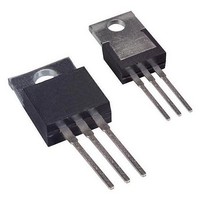
TISP3080H3SL-S Bourns Inc., TISP3080H3SL-S Datasheet

TISP3080H3SL-S
Specifications of TISP3080H3SL-S
Related parts for TISP3080H3SL-S
TISP3080H3SL-S Summary of contents
Page 1
TISP3xxxH3SL Overview This TISP ® device series protects central office, access and customer premise equipment against overvoltages on the telecom line. The TISP3xxxH3SL protects R-G and T-G. In addition, the device is rated for simultaneous R-G and T-G impulse conditions. ...
Page 2
TISP3xxxH3SL Overvoltage Protector Series ITU-T K.20/21 Rating . . . . . . . . 8 kV 10/700, 200 A 5/310 Ion-Implanted Breakdown Region Precise and Stable Voltage Low Voltage Overshoot under Surge V V DRM (BO) Device V V ...
Page 3
TISP3xxxH3SL Overvoltage Protector Series Absolute Maximum Ratings °C (Unless Otherwise Noted) Repetitive peak off-state voltage, (see Note 1) Non-repetitive peak on-state pulse current (see Notes 2, 3 and 4) 2/10 µs (GR-1089-CORE, 2/10 µs voltage wave ...
Page 4
TISP3xxxH3SL Overvoltage Protector Series Electrical Characteristics for the R and and G Terminals °C (Unless Otherwise Noted) Parameter Repetitive peak off DRM D state current V Breakover voltage dv/dt ...
Page 5
TISP3xxxH3SL Overvoltage Protector Series Electrical Characteristics for the R and T Terminals °C (Unless Otherwise Noted) Parameter Repetitive peak off DRM D state current V Breakover voltage dv/dt = ±750 V/ms, R ...
Page 6
TISP3xxxH3SL Overvoltage Protector Series Parameter Measurement Information V DRM -v I DRM I (BO) V (BO) Quadrant III Switching Characteristic Figure 1. Voltage- current Characteristic for Terminal Pairs JANUARY 1999 - REVISED JANUARY 2007 Specifications are subject to change without ...
Page 7
TISP3xxxH3SL Overvoltage Protector Series Typical Characteristics OFF-STATE CURRENT vs JUNCTION TEMPERATURE 100 V = ± 0·1 0·01 0·001 - Junction Temperature - °C J Figure 2. ON-STATE CURRENT vs ON-STATE ...
Page 8
TISP3xxxH3SL Overvoltage Protector Series Typical Characteristics NORMALIZED CAPACITANCE vs OFF-STATE VOLTAGE 1 0.9 0.8 0.7 0.6 0.5 '3070 THRU '3115 0.4 0.3 '3125 THRU '3210 '3250 THRU '3350 0.2 0 Off-state Voltage - ...
Page 9
TISP3xxxH3SL Overvoltage Protector Series Typical Characteristics V DRM DERATING FACTOR vs MINIMUM AMBIIENT TEMPERATURE 1.00 0.99 0.98 0.97 '3070 THRU '3115 0.96 0.95 '3125 THRU '3210 0.94 '3250 THRU '3350 0.93 -40 -35 -30 -25 -20 -15 - ...
Page 10
TISP3xxxH3SL Overvoltage Protector Series Impulse Testing To verify the withstand capability and safety of the equipment, standards require that the equipment is tested with various impulse wave forms. The table below shows some common values. Peak Voltage Standard Setting V ...
Page 11
TISP3xxxH3SL Overvoltage Protector Series Normal System Voltage Levels (continued) For the extreme case of an unconnected line, the temperature at which clipping begins can be calculated using the data from Figure 9. To possibly clip, the V value has to ...


