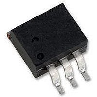
16TTS12SPBF Vishay, 16TTS12SPBF Datasheet - Page 3

16TTS12SPBF
Manufacturer Part Number
16TTS12SPBF
Description
SCRs 1200 Volt 16 Amp
Manufacturer
Vishay
Specifications of 16TTS12SPBF
Breakover Current Ibo Max
200 A
Rated Repetitive Off-state Voltage Vdrm
1200 V
Off-state Leakage Current @ Vdrm Idrm
0.5 mA
Forward Voltage Drop
1.4 V
Gate Trigger Voltage (vgt)
2 V
Maximum Gate Peak Inverse Voltage
10 V
Gate Trigger Current (igt)
60 mA
Holding Current (ih Max)
100 mA
Mounting Style
SMD/SMT
Package / Case
D2PAK
Peak Repetitive Off-state Voltage, Vdrm
1.2kV
Gate Trigger Current Max, Igt
90mA
Current It Av
10A
On State Rms Current It(rms)
16A
Peak Non Rep Surge Current Itsm 50hz
200A
Lead Free Status / RoHS Status
Lead free / RoHS Compliant
Note
(1)
Document Number: 94589
Revision: 08-Jun-10
THERMAL - MECHANICAL SPECIFICATIONS
PARAMETER
Maximum junction and storage
temperature range
Soldering temperature
Maximum thermal resistance,
junction to case
Typical thermal resistance,
junction to ambient
Approximate weight
Marking device
When mounted on 1" square (650 mm
For recommended footprint and soldering techniques refer to application note #AN-994.
125
120
115
110
105
100
125
120
115
110
105
100
95
90
95
90
0
0
Fig. 1 - Current Rating Characteristics
Fig. 2 - Current Rating Characteristics
2
Average On-state Current (A)
Average On-state Current (A)
2
4
30°
16TTS.. Series
R
30°
4
thJC
16TTS.. Series
R
60°
6
DiodesAmericas@vishay.com, DiodesAsia@vishay.com,
thJC
60°
For technical questions within your region, please contact one of the following:
(DC) = 1.3 °C/W
90°
8
6
(DC) = 1.3 °C/W
120°
Conduction Period
Conduction Angle
90°
10
8
180°
120°
2
12
) PCB of FR-4 or G-10 material 4 oz. (140 μm) copper 40 °C/W.
DC
180°
10
14
12
16
SYMBOL
Phase Control SCR, 16 A
T
R
R
J
, T
T
thJC
thJA
Surface Mountable
S
Stg
VS-16TTS..SPbF High Voltage Series
For 10 s (1.6 mm from case)
DC operation
PCB mount
Case style D
(1)
2
TEST CONDITIONS
PAK (SMD-220)
DiodesEurope@vishay.com
Fig. 3 - On-State Power Loss Characteristics
Fig. 4 - On-State Power Loss Characteristics
18
16
14
12
10
25
20
15
10
8
6
4
2
0
5
0
0
0
RMS Limit
1
RMS Limit
2
180°
120°
180°
120°
90°
60°
30°
Average On-state Current (A)
DC
90°
60°
30°
Average On-state Current (A)
2
4
3
Vishay Semiconductors
6
4
8
5
10
6
Conduction Period
Conduction Angle
16TTS.. Series
T = 125°C
J
16TTS.. Series
T = 125°C
7
12
J
8
- 40 to 125
14 16
VALUES
9 10 11
0.07
240
1.3
40
2
16TTS08S
16TTS12S
www.vishay.com
18
UNITS
°C/W
oz.
°C
g
3


