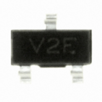
HBAT-5402-BLKG Avago Technologies US Inc., HBAT-5402-BLKG Datasheet - Page 3

HBAT-5402-BLKG
Manufacturer Part Number
HBAT-5402-BLKG
Description
DIODE SCHOTTKY 30V 220MA SOT-23
Manufacturer
Avago Technologies US Inc.
Specifications of HBAT-5402-BLKG
Mounting Type
Surface Mount
Voltage - Reverse Standoff (typ)
30V
Voltage - Breakdown
800V
Power (watts)
250mW
Polarization
Bidirectional
Package / Case
SOT-23-3, TO-236-3, Micro3™, SSD3, SST3
Speed
Fast Recovery =< 500ns, > 200mA (Io)
Voltage - Dc Reverse (vr) (max)
30V
Current - Average Rectified (io) (per Diode)
220mA (DC)
Diode Configuration
1 Pair Series Connection
Capacitance Ct
3pF
Diode Case Style
SOT-23
Pin Configuration
Series Pair
Breakdown Voltage Min
30V
Forward Voltage
800mV
Breakdown Voltage
30V
Capacitance, Junction
3 pF
Configuration
Series
Current, Forward
100 mA
Current, Surge
1 A
Package Type
SOT-23
Power Dissipation
250 mW
Primary Type
Schottky Barrier
Resistance, Thermal, Junction To Case
500 °C/W
Speed, Switching
Fast
Temperature, Junction, Maximum
+150 °C
Voltage, Forward
800 mV
Capacitance
3pF
Current Rating
220A
Diode Type
RF Schottky
Rohs Compliant
Yes
Lead Free Status / RoHS Status
Lead free / RoHS Compliant
Reverse Recovery Time (trr)
-
Current - Reverse Leakage @ Vr
-
Voltage - Forward (vf) (max) @ If
-
Lead Free Status / RoHS Status
Lead free / RoHS Compliant, Lead free / RoHS Compliant
Other names
516-1872
HBAT-5402-BLKG
HBAT-5402-BLKG
Available stocks
Company
Part Number
Manufacturer
Quantity
Price
Part Number:
HBAT-5402-BLKG
Manufacturer:
AVAGO/安华高
Quantity:
20 000
Typical Performance
Device Orientation
USER
FEED
DIRECTION
3
Figure 1. Forward Current vs. Forward Voltage at
Temperature for HBAT-5400 and HBAT-5402.
Figure 4. Junction Temperature vs. Current as a
Function of Heat Sink Temperature for HBAT-540B
and HBAT-540C.
Note: Data is calculated from SPICE parameters.
0.01
300
100
160
140
120
100
0.1
10
80
60
40
20
1
0
0
0
Max. safe junction temp.
REEL
V
V
F
0.1
100
F
– FORWARD VOLTAGE (V)
– FORWARD VOLTAGE (V)
COVER TAPE
0.2
200
For Outlines SOT-23/323
0.3
300
T
T
T
T
T
T
A
A
A
A
A
A
0.4
= +75C
= +25C
= –25C
400
= +75C
= +25C
= –25C
0.5
500
CARRIER
TAPE
0.6
600
8 mm
Figure 2. Forward Current vs. Forward Voltage at
Temperature for HBAT-540B and HBAT-540C.
Figure 5. Total Capacitance vs. Reverse Voltage.
Note: "AB" represents package marking code.
0.01
500
100
0.1
3.0
2.5
2.0
1.5
1.0
10
1
0
0
"C" represents date code.
V
0.2
F
ABC
V
– FORWARD VOLTAGE (V)
R
– REVERSE VOLTAGE (V)
5
0.4
4 mm
ABC
TOP VIEW
0.6
10
0.8
T
T
T
ABC
A
A
A
= +75C
= +25C
= –25C
1.0
15
1.2
ABC
1.4
20
END VIEW
Figure 3. Junction Temperature vs. Current as a
Function of Heat Sink Temperature for HBAT-5400
and HBAT-5402.
Note: Data is calculated from SPICE parameters.
160
140
120
100
80
60
40
20
0
0
Max. safe junction temp.
I
F
– FORWARD CURRENT (mA)
50
100
150
T
T
T
A
A
A
= +75C
= +25C
= –25C
200
250


