TISP1120H3BJR-S Bourns Inc., TISP1120H3BJR-S Datasheet
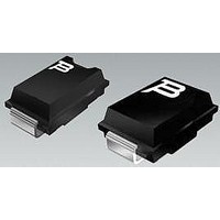
Sidacs -95VDRM 500A(IPP) -120VBO (R)

TISP1120H3BJR-S

Manufacturer Part Number
TISP1120H3BJR-S
Description
Sidacs -95VDRM 500A(IPP) -120VBO (R)
Manufacturer
Bourns Inc.
Datasheet

Specifications of TISP1120H3BJR-S

Breakover Current Ibo Max
70 A
Rated Repetitive Off-state Voltage Vdrm
95 V
Off-state Leakage Current @ Vdrm Idrm
0.005 mA
Mounting Style
SMD/SMT
Package / Case
DO-214AA
Lead Free Status / RoHS Status
Lead free / RoHS Compliant
*RoHS Directive 2002/95/EC Jan 27 2003 including Annex
Specifications are subject to change without notice.
Customers should verify actual device performance in their specific applications.
Low Capacitance
‘4015 ................................................................................... 78 pF
‘4030 ................................................................................... 62 pF
‘4040 ................................................................................... 59 pF
Digital Line Signal Level Protection
-ISDN
-xDSL
Safety Extra Low Voltage, SELV, values
100 A “H” Series specified for:
ITU-T recommendations K.20, K.45, K.21
FCC Part 68 and GR-1089-CORE
These devices are designed to limit overvoltages on digital telecommunication lines. Overvoltages are normally caused by a.c. power system
or lightning flash disturbances which are induced or conducted on to the telephone line. A single device provides 2-point protection and is
typically used for the protection of transformer windings and low voltage electronics.
The protector consists of a symmetrical voltage-triggered bidirectional thyristor. Overvoltages are initially clipped by breakdown clamping until
the voltage rises to the breakover level, which causes the device to crowbar into a low-voltage on-state condition. This low-voltage on state
causes the current resulting from the overvoltage to be safely diverted through the device. The device switches off when the diverted current
falls below the holding current value.
AUGUST 1999 - REVISED JANUARY 2007
Insert xx value corresponding to protecti o n voltages of 15 V, 30 V and 40 V.
Description
How to Order
TISP40xxH1BJ
Wave Shape
10/1000 µs
Device
10/160 µs
10/700 µs
10/560 µs
‘4015
‘4030
‘4040
Device
2/10 µs
8/20 µs
V
SMB (DO-214AA) Embossed Tape Reeled
± 15
± 25
ITU-T K.20/45/21
± 8
GR-1089-CORE
GR-1089-CORE
DRM
IEC 61000-4-5
V
FCC Part 68
FCC Part 68
FCC Part 68
Standard
Package
V
± 15
± 30
± 40
(BO)
V
I
400
200
150
125
500
100
TSP
A
Carrier
TISP40xxH1BJ VLV Overvoltage Protector Series
BIDIRECTIONAL THYRISTOR OVERVOLTAGE PROTECTORS
TISP 40xxH1BJR-S
Order As
TISP4015H1BJ, TISP4030H1BJ, TISP4040H1BJ
SMBJ Package (Top View)
Device Symbol
............................................ UL Recognized Components
Marking Code
alternative line designators of A and B
T erminals T and R correspond to the
40xxH1
R(B)
1
Std. Qty.
3000
T
R
SD4XAA
VERY LOW VOLTAGE
2
MDXXBGE
T(A)

Related parts for TISP1120H3BJR-S

TISP1120H3BJR-S Summary of contents

Page 1

Low Capacitance ‘4015 ................................................................................... 78 pF ‘4030 ................................................................................... 62 pF ‘4040 ................................................................................... 59 pF Digital Line Signal Level Protection -ISDN -xDSL Safety Extra Low Voltage, SELV, values V V DRM (BO) Device V V ‘4015 ± 8 ± 15 ‘4030 ...

Page 2

TISP40xxH1BJ VLV Overvoltage Protector Series Absolute Maximum Ratings Repetitive peak off-state voltage Non-repetitive peak on-state pulse current (see Notes 1 and 2) 2/10 µs (Telcordia GR-1089-CORE, 2/10 µs voltage wave shape) 8/20 µ 61000-4-5, ...

Page 3

TISP40xxH1BJ VLV Overvoltage Protector Series Electrical Characteristics Parameter MHz MHz Off-state capacitance off MHz, V Thermal Characteristics Parameter R Junction to free air thermal ...

Page 4

TISP40xxH1BJ VLV Overvoltage Protector Series Parameter Measurement Information V DRM -v I DRM I (BO) V (BO) Quadrant III Switching Characteristic Figure 1. Voltage-Current Characteristic for T and R Terminals All Measurements are Referenced to the R Terminal +i I ...

Page 5

TISP40xxH1BJ VLV Overvoltage Protector Series Typical Characteristics AUGUST 1999 - REVISED JANUARY 2007 Specifications are subject to change without notice. Customers should verify actual device performance in their specific applications. CAPACITANCE vs OFF-STATE VOLTAGE ...

Page 6

TISP40xxH1BJ VLV Overvoltage Protector Series Rating and Thermal Information NON-REPETITIVE PEAK ON-STATE CURRENT 1.5 vs CURRENT DURATION V = 600 Vrms, 50/60 Hz GEN R = 1.4*V /I GEN GEN TSM(t) EIA/JESD51-2 ENVIRONMENT ...

Page 7

TISP40xxH1BJ VLV Overvoltage Protector Series Transformer Protection The inductance of a transformer winding reduces considerably when the magnetic core material saturates. Saturation occurs when the magnetizing current through the winding inductance exceeds a certain value. It should be noted that ...

Page 8

TISP40xxH1BJ VLV Overvoltage Protector Series TISP ® Device Voltage Selection (Continued higher voltage protector might be chosen specifically to reduce the protector capacitive effects on the signal. Low energy short duration spikes will be clipped by the protector. ...

Page 9

TISP40xxH1BJ VLV Overvoltage Protector Series 4-Wire Digital Systems SIGNAL T1 Th1 Th5 Th2 DC FEED SIGNAL T2 Th3 Th6 Th4 TRANSFORMER COUPLED FOUR-WIRE INTERFACE cases, signal protection, Th5, Th6, Th9 and Th10, can be TISP4015H1 type devices with a 15 ...

Related keywords