MCR72-008 ON Semiconductor, MCR72-008 Datasheet

SCRs 600V 8A

MCR72-008

Manufacturer Part Number
MCR72-008
Description
SCRs 600V 8A
Manufacturer
ON Semiconductor
Datasheet

Specifications of MCR72-008

Breakover Current Ibo Max
100 A
Rated Repetitive Off-state Voltage Vdrm
600 V
Off-state Leakage Current @ Vdrm Idrm
0.01 mA
Forward Voltage Drop
2 V
Gate Trigger Voltage (vgt)
1.5 V
Maximum Gate Peak Inverse Voltage
5 V
Gate Trigger Current (igt)
0.2 mA
Holding Current (ih Max)
6 mA
Mounting Style
Through Hole
Package / Case
TO-220-3
Lead Free Status / RoHS Status
Lead free / RoHS Compliant

Available stocks

Company
Part Number
Manufacturer
Quantity
Price
Part Number:
MCR72-008
Manufacturer:
ON
Quantity:
18 000
MCR72-3, MCR72-6,
MCR72-8
Sensitive Gate Silicon
Controlled Rectifiers
Reverse Blocking Thyristors
temperature, light and speed control; process and remote controls;
warning systems; capacitive discharge circuits and MPU interface.
Features
Stresses exceeding Maximum Ratings may damage the device. Maximum
Ratings are stress ratings only. Functional operation above the Recommended
Operating Conditions is not implied. Extended exposure to stresses above the
Recommended Operating Conditions may affect device reliability.
1. V
MAXIMUM RATINGS
November, 2008 − Rev. 4
Peak Repetitive Off−State Voltage (Note 1)
(T
50 Hz to 60 Hz)
On-State RMS Current
(180 Conduction Angles; T
Peak Non-Repetitive Surge Current
(1/2 Cycle, 60 Hz, T
Circuit Fusing Considerations (t = 8.3 ms)
Forward Peak Gate Voltage
(t
Forward Peak Gate Current
(t
Forward Peak Gate Power
(t
Average Gate Power (t = 8.3 ms, T
83 C)
Operating Junction Temperature Range
Storage Temperature Range
Mounting Torque
Designed for industrial and consumer applications such as
Uniformity and Stability
Resistance, High Heat Dissipation and Durability
Integrated Circuits
Center Gate Geometry for Uniform Current Density
All Diffused and Glass-Passivated Junctions for Parameter
Small, Rugged Thermowatt Construction for Low Thermal
Low Trigger Currents, 200 mA Maximum for Direct Driving from
Pb−Free Packages are Available*
Semiconductor Components Industries, LLC, 20008
apply for zero or negative gate voltage; however, positive gate voltage shall
not be applied concurrent with negative potential on the anode. Blocking
J
DRM
= *40 to 110 C, Sine Wave,
10 ms, T
10 ms, T
10 ms, T
and V
C
C
C
= 83 C)
= 83 C)
= 83 C)
RRM
Rating
for all types can be applied on a continuous basis. Ratings
J
= 110 C)
(T
J
C
= 25 C unless otherwise noted)
Preferred Device
= 83 C)
MCR72−3
MCR72−6
MCR72−8
C
=
Symbol
I
P
V
V
T(RMS)
I
V
P
I
G(AV)
T
DRM,
TSM
RRM
I
GM
T
GM
GM
2
stg
J
t
−40 to +110
−40 to +150
Value
"5.0
0.75
100
400
600
100
8.0
1.0
5.0
8.0
40
1
in. lb.
Unit
A
W
W
V
A
A
V
A
C
C
2
s
See detailed marking, ordering, and shipping information in
the package dimensions section on page 5 of this data sheet.
Preferred devices are recommended choices for future use
and best overall value.
MARKING AND ORDERING INFORMATION
1
2
3
4
1
2
3
100 thru 600 VOLTS
8 AMPERES RMS
A
CASE 221A−09
http://onsemi.com
PIN ASSIGNMENT
TO−220AB
STYLE 3
CASE 221A−07
SCRs
TO−220AB
STYLE 3
Publication Order Number:
Cathode
Anode
Anode
Gate
G
1
2
K
3
MCR72/D

Related parts for MCR72-008

MCR72-008 Summary of contents

Page 1

... MCR72-3, MCR72-6, MCR72-8 Preferred Device Sensitive Gate Silicon Controlled Rectifiers Reverse Blocking Thyristors Designed for industrial and consumer applications such as temperature, light and speed control; process and remote controls; warning systems; capacitive discharge circuits and MPU interface. Features Center Gate Geometry for Uniform Current Density ...

Page 2

... Pb−Free strategy and soldering details, please download the ON Semiconductor Soldering and Mounting Techniques Reference Manual, SOLDERRM/D. http://onsemi.com 2 ...

Page 3

THERMAL CHARACTERISTICS Characteristic Thermal Resistance, Junction−to−Case Thermal Resistance, Junction−to−Ambient Maximum Lead Temperature for Soldering Purposes 1/8 from Case for 10 Secs ELECTRICAL CHARACTERISTICS Characteristic OFF CHARACTERISTICS Peak Repetitive Forward or Reverse Blocking Current (Note Rated V or ...

Page 4

Voltage Current Characteristic of SCR Symbol Parameter V Peak Repetitive Off State Forward Voltage DRM I Peak Forward Blocking Current DRM V Peak Repetitive Off State Reverse Voltage RRM I Peak Reverse Blocking Current RRM V Peak On State Voltage ...

Page 5

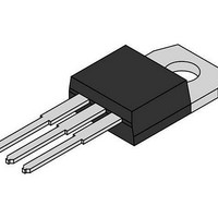
... MCR72−8G MCR72−8T MCR72−8TG MARKING DIAGRAMS TO−220AB CASE 221A− MCR72−6TG AKA A = Assembly Location Y = Year WW = Work Week MCR72−6T = Device Code G = Pb−Free Package AKA = Diode Polarity Package TO−220AB TO−220AB (Pb−Free) TO−220AB TO−220AB (Pb−Free) TO−220AB TO−220AB (Pb−Free) TO−220AB TO− ...

Page 6

PACKAGE DIMENSIONS TO−220 CASE ...

Page 7

... N. American Technical Support: 800−282−9855 Toll Free USA/Canada Europe, Middle East and Africa Technical Support: Phone: 421 33 790 2910 Japan Customer Focus Center Phone: 81−3−5773−3850 http://onsemi.com 7 ON Semiconductor Website: www.onsemi.com Order Literature: http://www.onsemi.com/orderlit For additional information, please contact your local Sales Representative MCR72/D ...

Related keywords