MBRF20200CTG ON Semiconductor, MBRF20200CTG Datasheet

DIODE SCHOTTKY 200V 10A TO220FP

MBRF20200CTG

Manufacturer Part Number
MBRF20200CTG
Description
DIODE SCHOTTKY 200V 10A TO220FP
Manufacturer
ON Semiconductor
Series
SWITCHMODE™r
Datasheet

Specifications of MBRF20200CTG

Voltage - Forward (vf) (max) @ If
900mV @ 10A
Current - Reverse Leakage @ Vr
1mA @ 200V
Current - Average Rectified (io) (per Diode)
10A
Voltage - Dc Reverse (vr) (max)
200V
Diode Type
Schottky
Speed
Fast Recovery =< 500ns, > 200mA (Io)
Diode Configuration
1 Pair Common Cathode
Mounting Type
Through Hole
Package / Case
TO-220-3 Full Pack (Straight Leads)
Product
Schottky Diodes
Peak Reverse Voltage
200 V
Forward Continuous Current
20 A
Max Surge Current
150 A
Configuration
Dual Common Cathode
Forward Voltage Drop
1 V
Maximum Reverse Leakage Current
1000 uA
Operating Temperature Range
- 65 C to + 150 C
Mounting Style
Through Hole
Lead Free Status / RoHS Status
Lead free / RoHS Compliant
Reverse Recovery Time (trr)
-
Lead Free Status / Rohs Status
Lead free / RoHS Compliant
Other names
MBRF20200CTGOS

Available stocks

Company
Part Number
Manufacturer
Quantity
Price
Part Number:
MBRF20200CTG
Manufacturer:
ON
Quantity:
4 250
Part Number:
MBRF20200CTG
Manufacturer:
ON Semiconductor
Quantity:
82
Part Number:
MBRF20200CTG
Manufacturer:
ON/安森美
Quantity:
20 000
Part Number:
MBRF20200CTG
0
Company:
Part Number:
MBRF20200CTG
Quantity:
3 000
Company:
Part Number:
MBRF20200CTG
Quantity:
2 500
MBRF20200CT
SWITCHMODEt
Schottky Power Rectifier
principle in a large area metal−to−silicon power diode.
State−of−the−art geometry features epitaxial construction with oxide
passivation and metal overlay contact. Ideally suited for use as
rectifiers in very low−voltage, high−frequency switching power
supplies, free wheeling diodes and polarity protection diodes.
Features
Mechanical Characteristics:
*For additional information on our Pb−Free strategy and soldering details, please
© Semiconductor Components Industries, LLC, 2008
August, 2008 − Rev. 7
download the ON Semiconductor Soldering and Mounting Techniques
Reference Manual, SOLDERRM/D.
The SWITCHMODE Power Rectifier employs the Schottky Barrier
Leads are Readily Solderable
260°C Max. for 10 Seconds
Highly Stable Oxide Passivated Junction
Very Low Forward Voltage Drop
Matched Dual Die Construction
High Junction Temperature Capability
High dv/dt Capability
Guardring for Stress Protection
Epoxy Meets UL 94 V−0 @ 0.125 in
Electrically Isolated. No Isolation Hardware Required.
Pb−Free Package is Available*
Case: Epoxy, Molded
Weight: 1.9 Grams (Approximately)
Finish: All External Surfaces Corrosion Resistant and Terminal
Lead Temperature for Soldering Purposes:
Preferred Device
1
Preferred devices are recommended choices for future use
and best overall value.
MBRF20200CT
MBRF20200CTG
Device
20 AMPERES, 200 VOLTS
1
2
SCHOTTKY BARRIER
A
Y
WW
B20200 = Device Code
G
AKA
3
ORDERING INFORMATION
2
MARKING DIAGRAM
http://onsemi.com
RECTIFIER
= Assembly Location
= Year
= Work Week
= Pb−Free Package
= Polarity Designator
(Pb−Free)
Package
B20200G
TO−220
TO−220
AYWW
A K A
ISOLATED TO−220
Publication Order Number:
CASE 221D
STYLE 3
MBRF20200CT/D
50 Units/Rail
50 Units/Rail
1
3
Shipping

Related parts for MBRF20200CTG

MBRF20200CTG Summary of contents

Page 1

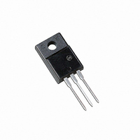
... Year WW = Work Week B20200 = Device Code G = Pb−Free Package AKA = Polarity Designator ORDERING INFORMATION Device Package MBRF20200CT TO−220 MBRF20200CTG TO−220 (Pb−Free) Preferred devices are recommended choices for future use and best overall value CASE 221D STYLE 3 Shipping 50 Units/Rail 50 Units/Rail Publication Order Number: ...

Page 2

MAXIMUM RATINGS (Per Leg) Peak Repetitive Reverse Voltage Working Peak Reverse Voltage DC Blocking Voltage Average Rectified Forward Current (Rated 125° Peak Repetitive Forward Current, Per Leg Nonrepetitive Peak Surge Current (Surge applied at ...

Page 3

TEST CONDITION FOR ISOLATION TEST* FULLY ISOLATED PACKAGE Figure 3. Mounting Position *Measurement made between leads and heatsink with all leads shorted together. MOUNTING INFORMATION Clip−Mounted Figure 4. Typical Mounting Technique http://onsemi.com 3 LEADS HEATSINK 0.110, MIN CLIP HEATSIN K ...

Page 4

... Opportunity/Affirmative Action Employer. This literature is subject to all applicable copyright laws and is not for resale in any manner. PUBLICATION ORDERING INFORMATION LITERATURE FULFILLMENT: Literature Distribution Center for ON Semiconductor P.O. Box 5163, Denver, Colorado 80217 USA Phone: 303−675−2175 or 800−344−3860 Toll Free USA/Canada Fax: 303− ...

Related keywords