STPS30L30CT STMicroelectronics, STPS30L30CT Datasheet

DIODE SCHOTTKY 30V 15A TO-220AB

STPS30L30CT

Manufacturer Part Number
STPS30L30CT
Description
DIODE SCHOTTKY 30V 15A TO-220AB
Manufacturer
STMicroelectronics
Datasheet

Specifications of STPS30L30CT

Voltage - Forward (vf) (max) @ If
460mV @ 15A
Current - Reverse Leakage @ Vr
1.5mA @ 60V
Current - Average Rectified (io) (per Diode)
15A
Voltage - Dc Reverse (vr) (max)
30V
Diode Type
Schottky
Speed
Fast Recovery =< 500ns, > 200mA (Io)
Diode Configuration
1 Pair Common Cathode
Mounting Type
Through Hole
Package / Case
TO-220-3 (Straight Leads)
Product
Schottky Diodes
Peak Reverse Voltage
30 V
Forward Continuous Current
30 A
Max Surge Current
220 A
Configuration
Dual Common Cathode
Forward Voltage Drop
0.57 V
Maximum Reverse Leakage Current
1500 uA
Operating Temperature Range
+ 150 C
Mounting Style
Through Hole
Lead Free Status / RoHS Status
Lead free / RoHS Compliant
Reverse Recovery Time (trr)
-
Lead Free Status / Rohs Status
Lead free / RoHS Compliant
Other names
497-2756-5

Available stocks

Company
Part Number
Manufacturer
Quantity
Price
Part Number:
STPS30L30CT
Manufacturer:
ST
Quantity:
4 000
Part Number:
STPS30L30CT
Manufacturer:
ST
0
Part Number:
STPS30L30CT
Manufacturer:
ST
Quantity:
20 000
Part Number:
STPS30L30CT
Manufacturer:
ST
Quantity:
8 300
Part Number:
STPS30L30CT
Manufacturer:
ST
Quantity:
9 722
Company:
Part Number:
STPS30L30CT
Quantity:
1 450
Company:
Part Number:
STPS30L30CT
Quantity:
14 000
Part Number:
STPS30L30CT-ST
Manufacturer:
ST
0
Part Number:
STPS30L30CT.
Manufacturer:
ST
0
Features
Description
This dual center tap Schottky rectifier is suited for
switch mode power supplies and high frequency
DC to DC converters.
Packaged in TO-220AB, D
device is intended for use in low voltage, high
frequency inverters, free-wheeling and polarity
protection applications.
Table 1.
April 2010
Very small conduction losses
Negligible switching losses
Extremely fast switching
Low forward voltage drop
Low thermal resistance
Avalanche capability specified
T
V
V
I
j
F
F(AV)
(max)
RRM
(typ)
Device summary
2
PAK and I
2 x 15 A
150 °C
0.37 V
30 V
2
PAK, this
Doc ID 5506 Rev 6
Low drop power Schottky rectifier
Figure 1.
a. V
operating area defined in
pulse measurements (t
are static characteristics
K
ARM
STPS30L30CT
V
AR
TO-220AB
V
and I
RRM
V
I
V
A1
ARM
R
Electrical characteristics
"Reverse"
A1
A2
must respect the reverse safe
STPS30L30CR
K
A2
2 x I
p
I
A1
STPS30L30C
I
I
2
F
< 1 µs). V
O
O
PAK
Figure 12
I
I
I
V To
R
AR
"Forward"
A2
K
K
V
STPS30L30CG
R
F(I o )
, I
V
R
K
AR
, V
D
A1
V
2
X
and I
RRM
PAK
F
X
V
AR
F(2xI o )
and V
(a)
www.st.com
are
V
A2
F
,
1/9
9

Related parts for STPS30L30CT

STPS30L30CT Summary of contents

Page 1

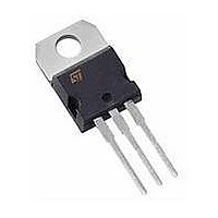
... Table 1. Device summary I F(AV) V RRM T (max (typ) F April 2010 Low drop power Schottky rectifier K TO-220AB STPS30L30CT 2 PAK, this Figure 150 °C 0. and I ARM operating area defined in pulse measurements (t are static characteristics Doc ID 5506 Rev 6 ...

Page 2

Characteristics 1 Characteristics Table 2. Absolute ratings (limiting values per diode) Symbol V Repetitive peak reverse voltage RRM I Forward rms current F(RMS) Average forward current δ = 0.5 I F(AV) I Surge non repetitive forward current t FSM I ...

Page 3

STPS30L30C Figure 2. Average forward power dissipation versus average forward current (per diode) PF(av)( δ = 0.2 δ = 0.1 8 δ IF(av) ( ...

Page 4

Characteristics Figure 8. Reverse leakage current versus reverse voltage applied (typical values per diode) IR(mA) 1E+3 Tj=150°C 1E+2 Tj=125°C 1E+1 1E+0 Tj=25°C 1E-1 VR(V) 1E Figure 10. Forward voltage drop versus forward current (maximum values per ...

Page 5

STPS30L30C 2 Package information ● Epoxy meets UL94, V0 ● Cooling method: by conduction (C) ● Recommended torque value: 0.4 to 0.6 N·m In order to meet environmental requirements, ST offers these devices in different grades of ® ECOPACK packages, ...

Page 6

Package information Mounting (soldering) the I IS NOT PERMITTED. A standard through-hole mounting is mandatory. 2 Table 6. I PAK dimensions 6/9 2 PAK metal slug (heatsink) with alloy, like a surface mount device ...

Page 7

STPS30L30C 2 Table 7. D PAK dimensions Figure 13. D PAK footprint (dimensions in mm) Ref FLAT ZONE NO LESS THAN ...

Page 8

... Ordering information 3 Ordering information Table 8. Ordering information Order code STPS30L30CT STPS30L30CG STPS30L30CG-TR STPS30L30CG-TR 4 Revision history Table 9. Document revision history Date Jul-2003 29-Apr-2010 8/9 Marking Package STPS30L30CT TO-220AB 2 STPS30L30CR D PAK 2 STPS30L30CG D PAK 2 STPS30L30CG I PAK Revision 5C Previous issue Added Figure 1 and 6 to Table 2. ...

Page 9

... STPS30L30C Information in this document is provided solely in connection with ST products. STMicroelectronics NV and its subsidiaries (“ST”) reserve the right to make changes, corrections, modifications or improvements, to this document, and the products and services described herein at any time, without notice. All ST products are sold pursuant to ST’s terms and conditions of sale. ...

Related keywords