BAS116V-7 Diodes Inc, BAS116V-7 Datasheet
BAS116V-7
Specifications of BAS116V-7
Available stocks


Related parts for BAS116V-7


BAS116V-7 Summary of contents
Page 1
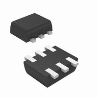
... T J STG = 25°C unless otherwise specified A Symbol Min Typ ⎯ (BR)R ⎯ ⎯ ⎯ ⎯ ⎯ ⎯ ⎯ www.diodes.com BAS116V SURFACE MOUNT LOW LEAKAGE DIODE TOP VIEW Value Unit 215 mA 500 mA 4.0 1.0 A 0.5 Value Unit 150 mW °C/W 833 °C -65 to +150 ...
Page 2
... Fig. 1 Power Derating Curve, Total Package 100 T , AMBIENT TEMPERATURE ( C) A Fig. 3 Typical Reverse Characteristics, Per Element Ordering Information (Note 6) Part Number BAS116V-7 Notes: 6. For packaging details our website at http://www.diodes.com/datasheets/ap02007.pdf. Marking Information Date Code Key Year 2004 2005 Code R S Month Jan ...
Page 3
... G 0.90 H 1.50 K 0. 0.10 All Dimensions Dimensions Value (in mm IMPORTANT NOTICE LIFE SUPPORT www.diodes.com BAS116V Max Typ 0.30 0.20 1.25 1.20 1.70 1.60 0.50 1.10 1.00 1.70 1.60 0.60 0.60 0.30 0.20 0.18 0.11 2.2 1.2 0.375 0.5 1.7 0.5 March 2008 © ...