STPS30L60CR STMicroelectronics, STPS30L60CR Datasheet
STPS30L60CR
Specifications of STPS30L60CR
Available stocks


Related parts for STPS30L60CR


STPS30L60CR Summary of contents
Page 1
... February 2011 PAK, STPS30L60CT ( F F(2xI o ) Table 1. V and I are and RRM F Doc ID 6479 Rev 9 STPS30L60C Power Schottky rectifier K TO-220FPAB STPS30L60CFP TO-220AB STPS30L60CR PAK TO-247 STPS30L60CG STPS30L60CW Device summary Symbol F(AV) V RRM T 150 °C j (max (max PAK Value 60 V 1/12 www.st.com 12 ...
Page 2
Characteristics 1 Characteristics Table 2. Absolute ratings (limiting values, per diode) Symbol V Repetitive peak reverse voltage RRM I Forward rms current F(RMS) I Average forward current F(AV) I Surge non repetitive forward current FSM I Repetitive peak reverse current ...
Page 3
STPS30L60C Table 4. Static electrical characteristics (per diode) Symbol Parameter (1) I Reverse leakage current R (1) V Forward voltage drop F 1. Pulse test : tp = 380 µs, δ < evaluate the conduction losses use the ...
Page 4
Characteristics Figure 6. Non repetitive surge peak forward current versus overload duration I (A) M 250 TO-220AB, TO-247 PAK PAK 200 maximum values, per diode 150 100 t(s) δ =0.5 0 1E-3 ...
Page 5
STPS30L60C Figure 12. Forward voltage drop versus forward current (maximum values, per diode) I (A) FM 200 100 Typical values Tj=150°C 10 Tj=125° 0.00 0.25 0.50 0.75 1.00 1.25 1.50 1.75 2.00 2.25 2.50 Figure 14. ...
Page 6
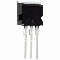
Package information 2 Package information ● Epoxy meets UL94, V0 ● Cooling method: by conduction (C) ● Recommended torque values: TO-220AB and TO-220FPAB 0.4 to 0.6 N·m, TO-247 0.55 N·m (1.0 N·m maximum) In order to meet environmental requirements, ST ...
Page 7
STPS30L60C Table 6. TO-220AB dimensions H2 Dia Doc ID 6479 Rev 9 Package information Dimensions Ref. Millimeters Min. Max. Min. A 4.40 4.60 0.173 ...
Page 8
Package information 2 Table 7. D PAK dimensions Figure 15. Footprint (dimensions in millimeters) 8/ FLAT ZONE NO LESS THAN 2mm 16.90 ...
Page 9
STPS30L60C 2 Devices in I PAK with nickel-plated back frame must NOT be mounted by frame soldering like SMDs. Such devices are intended to be through-hole mounted ONLY and in no circumstances shall ST be held liable for any lack ...
Page 10
Package information Table 9. TO-247 dimensions F(x3) G 10/12 Ref Dia ...
Page 11
... Marking Package STPS30L60CW TO-247 STPS30L60CT TO-220AB 2 STPS30L60CG D PAK 2 STPS30L60CG D PAK 2 STPS30L60CR I PAK STPS30L60CFP TO-220FPAB Revision Description of changes 3B Initial release Reformatted to current standards. Corrected dimensions for PAK in Table 5. Added TO-220FPAB package. Added STPS30L60CG- ordering information. 6 Updated thermal parameters in Table 2. ...
Page 12
... Information in this document is provided solely in connection with ST products. STMicroelectronics NV and its subsidiaries (“ST”) reserve the right to make changes, corrections, modifications or improvements, to this document, and the products and services described herein at any time, without notice. All ST products are sold pursuant to ST’s terms and conditions of sale. ...