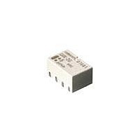
G6KU-2F-RF DC24 Omron, G6KU-2F-RF DC24 Datasheet

G6KU-2F-RF DC24
Specifications of G6KU-2F-RF DC24
G6KU2FRFDC24
Related parts for G6KU-2F-RF DC24
G6KU-2F-RF DC24 Summary of contents
Page 1
... G6K-2F G6K-2F-Y G6K-2G G6K-2G-Y G6K-2P G6K-2P-Y Resistive load (cosφ=1) 0 125 VAC VDC Ag (Au clad 125 VAC, 60 VDC 1 A 37.5 VA, 30W 10 μ mVDC RC Single coil latching 3.2 mm coil-contact terminal spacing G6KU-2F-Y G6KU-2G-Y G6KU-2P-Y G6K 67 Low Signal Relay ...
Page 2
... G6KU- 3.2 mm spacing, single coil latching (G6KU-2F-Y, G6KU-2G-Y, G6KU-2P-Y) Rated voltage Rated current Coil resistance (VDC) (mA) (Ω) 3 33.0 91 4.5 23.2 194 5 21.1 237 6 17.6 341 9 11.3 795 12 9 ...
Page 3
... Note: The tests were conducted at an ambient temperature of 23°C. Ambient Temperature vs. Switching Current Ambient temperature (°C) Ambient Temperature vs. Must Set or Must Reset Voltage G6KU-2G (F/P)-Y Max. estimated value Ambient temperature (°C) Electrical Service Life (Contact Resistance) (See note.) G6K-2G (F/P), G6K-2G (F/P)-Y NO ...
Page 4
Contact Reliability Test (See note.) G6K-2G (F/P), G6K-2G (F/P)-Y NO Sample: G6K-2G contact Number of Relays Test conditions resistive load at contact 10 mVDC with an operation rate Switching frequency: 7,200 operations/h 3 ...
Page 5
Must Operate and Must Release Time Distribution (See note.) G6K-2G (F/P), G6K-2G (F/P)-Y Sample: G6K-2G Must operate Number of Relays: 50 Must release time Time (ms) Note: The tests were conducted at an ambient temperature of 23°C. ■ Approvals UL ...
Page 6
... Note: Each value has a tolerance of ±0.3 mm. G6K-2P-Y Note: Each value has a tolerance of ±0.3 mm. G6KU-2F-Y Note: Each value has a tolerance of ±0.3 mm. G6KU-2G-Y Note: Each value has a tolerance of ±0.3 mm. G6KU-2P-Y Note: Each value has a tolerance of ±0.3 mm. G6K 72 Low Signal Relay Mounting Dimensions (Top View) Terminal Arrangement/ Internal Connections Tolerance: ± ...
Page 7
... Carrier tape Emboss tape 2. Reel Dimensions Stopper (green) 3. Carrier Tape Dimensions G6K-2F, G6K-2F-Y, G6KU-2F-Y Orientation mark Pulling direction G6K-2G, G6K-2G-Y, G6KU-2G-Y 50 pcs per anti-static tube 900 pcs per reel 2 reels per box Order in box multiples (see details below) G6K 73 Low Signal Relay ...
Page 8
... Time (s) • The thickness of cream solder to be applied should be within a range between 150 and 200 μm on OMRON’s recommended PCB pattern. • In order to perform correct soldering recommended that the correct soldering conditions be maintained as shown below on the left side. Correct Soldering ...
Page 9
Must not cause thermal changes in or deterioration of the insulating material. • Must not cause damage to other control devices. • Must not cause any harmful effect on people. • Must not cause fire. Therefore, be sure to ...
Page 10
MEMO G6K 76 Low Signal Relay ...
Page 11
... Seller within 30 days of receipt of shipment. III. PRECAUTIONS 1. Suitability THE BUYER’S SOLE RESPOINSIBILITY TO ENSURE THAT ANY OMRON PRODUCT IS FIT AND SUFFICIENT FOR USE IN A MOTORIZED VEHICLE APPLICATION. BUYER SHALL BE SOLELY RESPONSIBLE FOR DETERMINING APPROPRIATENESS OF THE PARTICULAR PRODUCT WITH RESPECT TO THE BUYER’ ...
Page 12
... THE OMRON PRODUCT IS PROPERLY RATED AND INSTALLED FOR THE INTENDED USE WITHIN THE OVERALL EQUIPMENT OR SYSTEM. Complete “Terms and Conditions of Sale” for product purchase and use are on Omron’s website at http://www.components.omron.com – under the “About Us” tab, in the Legal Matters section. ...


