FDLL333 Fairchild Semiconductor, FDLL333 Datasheet - Page 7
FDLL333
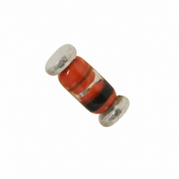
Manufacturer Part Number
FDLL333
Description
DIODE 125V 200MA LL34
Manufacturer
Fairchild Semiconductor
Datasheet
1.FDLL300A.pdf
(9 pages)
Specifications of FDLL333
Voltage - Forward (vf) (max) @ If
1.15V @ 300mA
Voltage - Dc Reverse (vr) (max)
125V
Current - Average Rectified (io)
200mA
Current - Reverse Leakage @ Vr
3nA @ 125V
Diode Type
Standard
Speed
Small Signal =< 200mA (Io), Any Speed
Capacitance @ Vr, F
6pF @ 0V, 1MHz
Mounting Type
Surface Mount
Package / Case
MELF (LL-34)
Product
Standard Recovery Rectifier
Configuration
Single
Reverse Voltage
150 V
Forward Voltage Drop
1.15 V @ 0.3 A
Forward Continuous Current
0.2 A
Max Surge Current
4 A
Reverse Current Ir
0.003 uA @ 125 V
Power Dissipation
0.5 W
Mounting Style
SMD/SMT
Maximum Operating Temperature
+ 175 C
Minimum Operating Temperature
- 65 C
Lead Free Status / RoHS Status
Lead free / RoHS Compliant
Reverse Recovery Time (trr)
-
Lead Free Status / Rohs Status
Lead free / RoHS Compliant
Available stocks
Company
Part Number
Manufacturer
Quantity
Price
Company:

Part Number:
FDLL333
Manufacturer:
Fairchild Semiconductor
Quantity:
9 460
Part Number:
FDLL333
Manufacturer:
FAIRCHILD/仙童
Quantity:
20 000


LL-34 Tape and Reel Data,continued
Notes: A0, B0, and K0 dimensions are determined with respect to the EIA/Jedec RS-481
LL-34 Embossed Carrier Tape
Configuration: Figure 3.0
LL-34 Carton Reel Configuration: Figure 4.0
Tape Size
8mm
8mm
Pkg type
(8mm)
LL-34
T
Tc
rotational and lateral movement requirements (see sketches A, B, and C).
K0
Wc
7" Dia
13" Dia
Option
1.7
+/-0.10
Reel
A0
20 deg maximum component rotation
3.7
+/-0.10
B0
7.00
178
13.00
330
Dim A
B0
Sketch A (Side or Front Sectional View)
Component Rotation
W2 max Measured at Hub
8.0
+/-0.3
0.059
1.5
0.059
1.5
Dim B
W
Dim N
W1 Measured at Hub
1.5
+/-0.10
D0
512 +0.020/-0.008
13 +0.5/-0.2
512 +0.020/-0.008
13 +0.5/-0.2
Dimensions are in inches and millimeters
A0
Dim C
1.1
+/-0.10
W3
User Direction of Feed
D1
Dimensions are in millimeter
Dim A
Dim D
P0
Max
1.75
+/-0.10
min
E1
0.795
20.2
0.795
20.2
Dim D
B0
P1
Sketch B (Top View)
Component Rotation
6.25
min
E2
7" Diameter Option
2.165
55
4.00
100
Dim N
D0
A0
D1
3.50
+/-0.05
DETAIL AA
20 deg maximum
F
0.331 +0.059/-0.000
8.4 +1.5/0
0.331 +0.059/-0.000
8.4 +1.5/0
Typical
component
center line
Typical
component
cavity
center line
4.0
+/-0.1
Dim W1
P1
B Min
Dim C
See detail AA
4.05
+/-0.05
P0
Dim W2
0.567
14.4
0.567
14.4
1.7
+/-0.10
K0
Sketch C (Top View)
Component lateral movement
0.5mm
maximum
0.3
+/-0.05
F
0.311 – 0.429
7.9 – 10.9
0.311 – 0.429
7.9 – 10.9
Dim W3 (LSL-USL)
T
E1
E2
0.5mm
maximum
W
January 2000, Rev. B
5.5
+/-0.2
Wc
0.10
max
Tc
Related parts for FDLL333
Image
Part Number
Description
Manufacturer
Datasheet
Request
R

Part Number:
Description:
Fairchild Semiconductor [IGBT MODULE]
Manufacturer:
Fairchild Semiconductor
Datasheet:

Part Number:
Description:
Discrete Semiconductor Modules
Manufacturer:
Fairchild Semiconductor
Part Number:
Description:
Discrete Semiconductor Modules
Manufacturer:
Fairchild Semiconductor
Part Number:
Description:
This N-Channel MOSFET is produced using Fairchild Semiconductor’s advanced Power Trench® process
Manufacturer:
Fairchild Semiconductor
Datasheet:
Part Number:
Description:
This N-Channel MOSFET is produced using Fairchild Semiconductor’s advanced Power Trench® process
Manufacturer:
Fairchild Semiconductor
Datasheet:
Part Number:
Description:
This N-Channel MOSFET is produced using Fairchild Semiconductor’s advanced PowerTrench® process
Manufacturer:
Fairchild Semiconductor
Datasheet:
Part Number:
Description:
This N-Channel MOSFET is produced using Fairchild Semiconductor’s advanced PowerTrench® process
Manufacturer:
Fairchild Semiconductor
Datasheet:
Part Number:
Description:
This N-Channel MOSFET is produced using Fairchild Semiconductor’s advanced Power Trench® process
Manufacturer:
Fairchild Semiconductor
Datasheet:
Part Number:
Description:
This N-Channel logic Level MOSFETs are produced using Fairchild Semiconductor‘s advanced Power Trench® process that has been special tailored to minimize the on-state resistance and yet maintain superior switching performance
Manufacturer:
Fairchild Semiconductor
Datasheet:
Part Number:
Description:
This N-Channel MOSFET is produced using Fairchild Semiconductor’s advanced Power Trench® process
Manufacturer:
Fairchild Semiconductor
Datasheet:
Part Number:
Description:
This N-Channel SyncFET™ is produced using Fairchild Semiconductor’s advanced PowerTrench® process
Manufacturer:
Fairchild Semiconductor
Datasheet:
Part Number:
Description:
This N-Channel SyncFET™ is produced using Fairchild Semiconductor’s advanced PowerTrench® process
Manufacturer:
Fairchild Semiconductor
Datasheet:
Part Number:
Description:
This N-Channel SyncFET™ is produced using Fairchild Semiconductor’s advanced PowerTrench® process
Manufacturer:
Fairchild Semiconductor
Datasheet:
Part Number:
Description:
This N-Channel logic Level MOSFETs are produced using Fairchild Semiconductor‘s advanced Power Trench® process that has been special tailored to minimize the on-state resistance and yet maintain superior switching performance
Manufacturer:
Fairchild Semiconductor
Datasheet:
Part Number:
Description:
This N-Channel MOSFET is produced using Fairchild Semiconductor’s advanced Power Trench® process that has been especially tailored to minimize the on-state resistance and yet maintain superior switching performance
Manufacturer:
Fairchild Semiconductor
Datasheet: