B57464S209M EPCOS Inc, B57464S209M Datasheet
B57464S209M
Specifications of B57464S209M


Related parts for B57464S209M


B57464S209M Summary of contents
Page 1
NTC thermistors for inrush current limiting Leaded and coated disks Series/Type: B57464 Date: May 2009 © EPCOS AG 2009. Reproduction, publication and dissemination of this publication, enclosures hereto and the information contained therein without EPCOS' prior express consent is prohibited. ...
Page 2
... Options Resistance tolerance <20%, alternative lead configurations and resistance ratings available on request Delivery mode Bulk General technical data Climatic category Max. power Resistance tolerance Rated temperature Dissipation factor Thermal cooling time constant Heat capacity Electrical specification and ordering codes max 25/100 (0 ...
Page 3
... When loaded with maximum allowable current/power and the specified dissipation factor is taken as a basis, the NTC thermistor may reach a mean temperature 250 C. The heat developed during operation will also be dissipated through the lead wires. So the contact areas, too, may become quite hot at maximum load. ...
Page 4
Inrush current limiters ICLs Taping and packing 1 Taping of radial leaded NTC thermistors Dimensions and tolerances Lead spacing F = 5.0 mm (taping to IEC 60286-2) Lead spacing F = 7.5 mm (taping based on IEC 60286-2) Please read ...
Page 5
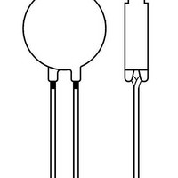
Inrush current limiters ICLs Dimensions (mm) Lead Tolerance of spacing lead spacing 11.5 max. th 6.0 max. d 0.5/0.6 0.05 P 12.7 0 3.85 0 5.0 +0.6/ 0 2.0 ...
Page 6
Inrush current limiters ICLs Types of packing Ammo packing Packing unit: 1000 - 2000 pcs./reel Reel packing Packing unit: 1000 - 2000 pcs./reel Reel dimensions (in mm) Reel type d I 360 max. II 500 max. Please read Cautions and ...
Page 7
Inrush current limiters ICLs Bulk packing The components are packed in cardboard boxes, the size of which depends on the order quantity. 2 Packing codes The last two digits of the complete ordering code state the packing mode: Last two ...
Page 8
... Leaded NTC thermistors Leaded thermistors comply with the solderability requirements specified by CECC. When soldering, care must be taken that the NTC thermistors are not damaged by excessive heat. The following maximum temperatures, maximum time spans and minimum distances have to be observed: Bath temperature ...
Page 9
... Inrush current limiters ICLs Wave soldering Temperature characteristic at component terminal with dual wave soldering 2 Robustness of terminations The leads meet the requirements of IEC 60068-2-21. They may not be bent closer than 4 mm from the solder joint on the thermistor body or from the point at which they leave the feed- throughs ...
Page 10
... When thermistors are sealed, potted or overmolded, there must be no mechanical stress caused by thermal expansion during the production process (curing / overmolding process) and during later operation. The upper category temperature of the thermistor must not be exceeded. Ensure that the materials used (sealing / potting compound and plastic material) are chemically neutral. ...
Page 11
... See "Important notes" at the end of this document. Storage Store thermistors only in original packaging. Do not open the package before storage. Storage conditions in original packaging: storage temperature humidity 75% annual mean, maximum 95%, dew precipitation is inadmissible. Avoid contamination of thermistors surface during storage, handling and processing. ...
Page 12
... Electrode must not be scratched before/during/after the mounting process. Contacts and housings used for assembly with thermistor have to be clean before mounting. During operation, the inrush current limiters surface temperature can be very high. Ensure that adjacent components are placed at a sufficient distance from the thermistor to allow for proper cooling of the thermistors ...
Page 13
... P Maximum power within stated max temperature range R Load resistance load R Rated resistance Resistance tolerance Series resistance S R Resistance at temperature T T (e. resistance Temperature t Time T Ambient temperature A t Thermal threshold time a T Upper category temperature max Please read Cautions and warnings and Important notes at the end of this document. ...
Page 14
... Inrush current limiters ICLs Symbol English T min Lower category temperature T Rated temperature R T Surface temperature surf V Voltage V Load voltage load V Voltage drop across an NTC thermistor Spannungsabfall am Heißleiter NTC V Root-mean-square value of voltage RMS Temperature coefficient Tolerance, change Dissipation factor th Thermal cooling time constant ...
Page 15
Important notes The following applies to all products named in this publication: 1. Some parts of this publication contain statements about the suitability of our products for certain areas of application. These statements are based on our knowledge of typical ...