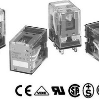
MY2-02-AC100/110 Omron, MY2-02-AC100/110 Datasheet

MY2-02-AC100/110
Specifications of MY2-02-AC100/110
Related parts for MY2-02-AC100/110
MY2-02-AC100/110 Summary of contents
Page 1
... Note: 1. When ordering, add the rated coil voltage to the model number(s), followed by “(S)”. Rated coil voltages are given in the coil ratings table. Example: MY2 AC12(S) ↑ Rated coil voltage 2. Arc barrier standard on all four-pole relays. ...
Page 2
... AC coil resistance and impedance are provided as reference values (at 60 Hz). 4. Power consumption drop was measured for the above data. When driving transistors, check leakage current and connect a bleeder re- sistor if required. 5. Rated voltage denoted by “*” will be manufactured upon request. Ask your OMRON representative. ■ Contact Ratings Item ...
Page 3
Characteristics Contact resistance Operate time Release time Max. operating frequency Mechanical 18,000 operations/hr Electrical Insulation resistance Dielectric withstand voltage Vibration resistance Shock resistance Life expectancy Ambient temperature Operating Ambient humidity Operating Weight Note: The values given above are initial ...
Page 4
... VDC 500 300 30 VDC 100 250 VAC Switching current (A) 262 General-purpose Relay MY4, MY4Z DC inductive load (L/R=7 ms) Switching voltage (V) MY2 (Inductive Loads) 10000 5000 3000 250 VAC 1000 500 30 VDC 300 250 VAC 100 MY4 (Inductive Loads) 10000 5000 3000 ...
Page 5
MY4Z (Resistive Loads) 10000 5000 3000 1000 250 VAC 500 300 30 VDC 100 30 VDC 50 250 VAC 30 10 Switching Current (A) MY4Z (Inductive Loads) 10000 5000 3000 1000 30 VDC 500 300 30 VDC 100 250 VAC ...
Page 6
... Dimensions Note: All units are in millimeters unless otherwise indicated. ■ 2-Pole Models MY2N ■ 4-Pole Models MY4N ■ Models with Test Button MY2IN MY4IN 264 General-purpose Relay 2.6 Eight, 1.2 dia. × 2.2 long holes 0.5 28 max. 6.4 36 max. 21.5 max. ...
Page 7
... Terminal Arrangement/Internal Connections (Bottom View) MY2 MY2N/MY2IN (AC Models) MY2N-CR/MY2IN-CR (AC Models Only) MY4(Z) MY4(Z)N/MY4(Z)IN (AC Models) MY4(Z)N-CR/MY4(Z)IN-CR (AC Models Only) MY2N/MY2IN MY2N-D2/MY2IN-D2 (DC Models) (DC Models Only) MY2N1/MY2IN1 MY2N1-D2/MY2IN1-D2 (DC Models Only) (DC Models Only) MY4(Z)N/MY4(Z)IN MY4(Z)N-D/MY4(Z)IN-D2 (DC Models) (DC Models Only) MY4(Z)N1/MY4(Z)IN1 MY4(Z)N1-D2/MY4(Z)N1-D2 (DC Models Only) (DC Models Only) MY General-purpose Relay 265 ...
Page 8
... The maximum operating ambient temperature for the PYF08A-N and PYF14A-N is 55°C. 4. When using the PYF08A-N or PYF14A operating ambient temperature exceeding 40°C, reduce the current to 60%. 5. The MY2(S) can be used at 70°C with a carry current ■ Socket Hold-down Clip Pairing Relay type ...
Page 9
Mounting Plates for Sockets Socket model For 1 socket PY08, PY14 PYP-1 Note: PYP-18 and PYP-36 can be cut into any desired length in accordance with the number of Sockets. ■ DIN Rail Track and Accessories Description Mounting rail ...
Page 10
Dimensions Unit: mm (inch) Socket Dimensions PYF08A-E Two, 4 Eight mounting sems screws holes 72 max. 23 max. PYF14A-E Two, 4 mounting holes 72 max. 29.5 max. PY08/PY08-Y1 (See note) 42 max. ...
Page 11
Socket Dimensions PYF08A-N 22 max max. PYF-08A PYF14A ...
Page 12
... General-purpose Relay Terminal arrangement/ internal connections (top view) 36.5 max. Note: Pole-2 and pole-3 can- not be used with the MY2 type. Use pole-1 (terminal numbers 11, 14, 12) and pole-4 (terminal numbers 41, 44, 42). 38.2 max. 36.5 max. (5.3) Color of insulating ...
Page 13
Clip and Release Levers PYCM-14S PYF14S Lever 26.5 typ. 21.5 typ. ■ Hold-down Clips PYC-A1 PYC-A1 (2 pcs per set) (2 pcs per set) 36.3 4.5 1.2 4.5 PYC-P PYC max. 3.3 38.5 PYCM-08S PYF08S Lever 28 ...
Page 14
Mounting Plates for Back-connecting Sockets PYP-1 PYP-1 Two, 3.4-dia. holes t=1.6 PYP-18 PYP-18 72 elliptical holes ■ Mounting Track and Accessories DIN Rail Track PFP-50N/PFP-100N Note: The figure in the parentheses is for PFP-50N. PFP-100N2 End Plate PFP-M 272 ...
Page 15
Spacer PFP-S ■ Approved Standards VDE Recognitions (File No. 112467UG, IEC 255, VDE 0435) No. of poles Coil ratings 2 6, 12, 24, 48/50, 100/110 110/120, 200/220, 220/240 VAC 4 6, 12, 24, 48, 100/110, 125 VDC UL Recognized (File ...
Page 16
SEV Listings (File No. 99.5 50902.01) No. of poles Coil ratings 240 VAC 6 to 125 VDC 4 Note: 1. The rated values approved by each of the safety standards (eg., UL, CSA, VDE, and SEV) may ...
Page 17
Examples of Applicable Wires (Confirmed Using Catalog Information) Type of wire Conductor type Equipment wire 2491X Flexible BS6004 Solid Switchgear BS6231 Solid Switchgear BS6231 Flexible Tri-rated control and switchgear Flexible Conduit Stranded UL1007 Flexible UL1015 Flexible UL1061 Flexible UL1430 Flexible ...
Page 18
Precautions Precautions for Connection • Do not move the screwdriver up, down, or from side to side while it is inserted in the hole. Doing so may cause damage to internal components (e.g., deformation of the coil spring or ...
Page 19
... Seller within 30 days of receipt of shipment. III. PRECAUTIONS 1. Suitability THE BUYER’S SOLE RESPOINSIBILITY TO ENSURE THAT ANY OMRON PRODUCT IS FIT AND SUFFICIENT FOR USE IN A MOTORIZED VEHICLE APPLICATION. BUYER SHALL BE SOLELY RESPONSIBLE FOR DETERMINING APPROPRIATENESS OF THE PARTICULAR PRODUCT WITH RESPECT TO THE BUYER’ ...
Page 20
... THE OMRON PRODUCT IS PROPERLY RATED AND INSTALLED FOR THE INTENDED USE WITHIN THE OVERALL EQUIPMENT OR SYSTEM. Complete “Terms and Conditions of Sale” for product purchase and use are on Omron’s website at http://www.components.omron.com – under the “About Us” tab, in the Legal Matters section. ...


